
You are here: Start » Technical Issues » Working with Modbus TCP Devices
Working with Modbus TCP Devices
Introduction
The filters for Modbus over TCP communication are located in the System :: Modbus TCP
Establishing Connection
To communicate with a ModbusTCP device, first, a connection needs to be established. The ModbusTCP_Connect filter should be used for establishing the connection. The default port for ModbusTCP protocol is 502. Usually, a connection is created before the application enters its main loop and it remains valid through multiple iterations of the process. It becomes invalid when it is explicitly closed using ModbusTCP_Close filter or when an I/O error occurs.
The Modbus filters work on the same socket as TCP IP filters. Therefore, it might happen that in case of the connection issues, information about TCP IP errors will appear.
If Modbus device supports Keep-Alive mechanism it is recommended to enable it to increase chance of detecting a broken connection. For more details, please read Using TCP/IP Communication.
Reading and Writing Values
FabImage Studio provides set of filters to manage Modbus objects. The following is table of object types provided by Modbus:
| Object Type | Access | Size |
|---|---|---|
| Coil | Read-Write | 1-bit |
| Discrete Input | Read-Only | 1-bit |
| Input Register | Read-Only | 16-bits |
| Holding Register | Read-Write | 16-bits |
The Coils, Inputs and Registers in ModbusTCP protocol are addressed starting at zero. The table below lists filters to control object types mentioned above.
Sample Application
The following example illustrates how to use ModbusTCP filters.
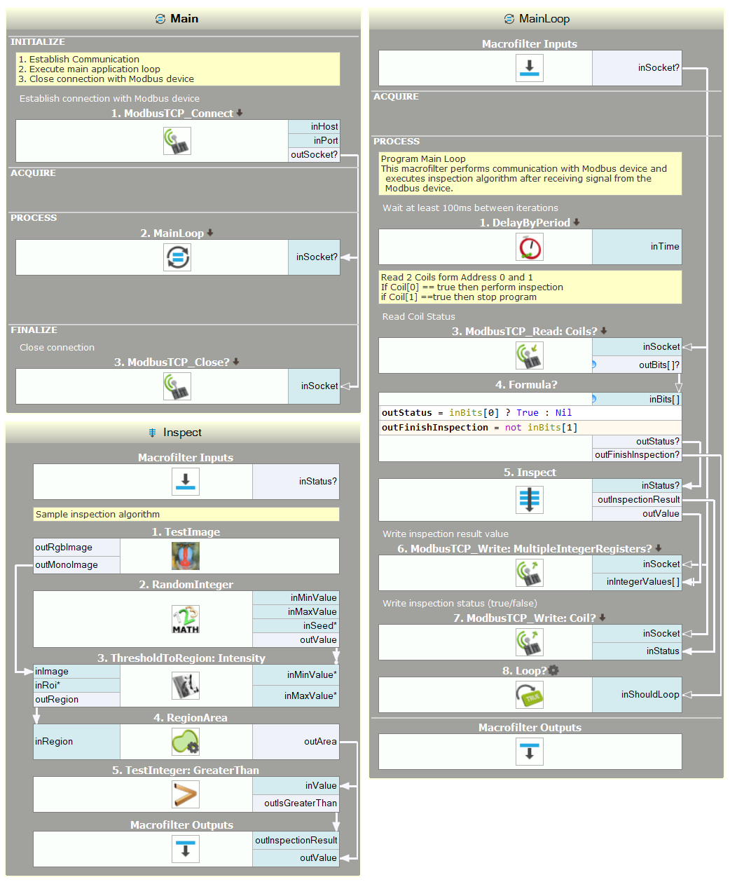
Main macrofilter - establish and close connection
Main Loop - communication with Modbus device
Inspection - sample inspection algorithm
Custom Functions
To support device-specific functions, FabImage Studio provides ModbusTCP_SendBuffer filter. This filter allows you to create a custom Modbus frame.
| Previous: Working with National Instruments Devices | Next: Communicating over OPC UA |