
You are here: Start » Technical Issues » Working with GigE Vision® Devices » Connecting Devices
Connecting Devices
Connecting a GigE Vision device to a computer means plugging both into the same Ethernet network.
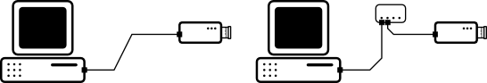
It is recommended that the connection is as simple as possible. To achieve best performance use direct connection with a crossed Ethernet cable or connect the camera and the computer to the same Ethernet switch (without any other heavy traffic routed through the same switch).
The device and the computer must reside in a single local area network and must be set up for the same subnet.
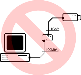
GigE Vision® is designed for 1 Gb/s networks, but it is also possible to use 100 Mb/s connection as long as the entire network connection have an uniformed speed (some custom device configuration might be required when the device is not able to detect connection speed automatically). It is recommended however to avoid connecting a device to a network link which is faster than the maximum throughput of the whole network route. Such configurations require manual setting of the device's transmission speed limit.
Firewall Issues
GigE Vision® protocol produces a specific type of traffic that is not firewall friendly. Typical firewall software is unable to recognize that video streaming traffic is initialized by a local application and will block this connection. FabImage's GigE driver attempts to overcome this problem using firewall traversal mechanism, but not all devices support this.
It is thus required to enable incoming traffic on all UDP ports for FabImage Studio and FabImage Executor in a firewall on your local computer.
For information how to enable such traffic in Windows Firewall see: Enabling Traffic in Firewall.
Configuring IP Address of a Device
In most situations a GigE Vision device is able to automatically obtain an IP address without user action (using DHCP server or automatic local link address). It is however recommended to set a static IP address for both local network card and device whenever possible. In some cases (e.g. when preparing the device for operation in an industrial network) it might be required to access and set/change the device's network configuration for a proper static IP address. Most suitable for this purpose will be a software and a documentation provided by the device manufacturer. When these are not available FabImage Studio offers universal configuration tools available from the GigE Vision Device Manager (see: Device Manager section).
Packet Size
Network video stream is divided into packets of a specified size. The packet size is limited by the Ethernet standard but some network cards support an extension called jumbo packet that increases allowed packet size. Because a connection is more efficient when the packet size is bigger, the application will attempt to negotiate biggest possible network packet size for current connection, taking advantage of enabled jumbo packets.
For information how to enable jumbo packets see: Enabling Jumbo Packets
Connecting Multiple Devices to a Single Computer
It is possible to connect multiple GigEVision cameras to a single computer and to perform image processing based on multiple video streams (e.g. observing objects from multiple sides), however it can introduce multiple technical challenges that must be considered.
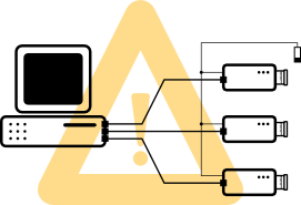
For the best performance it is recommended to connect all devices directly to the computer using multiple gigabit network cards:
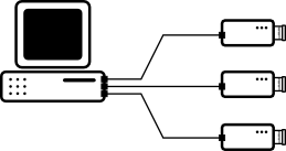
In such configuration it is required for the computer hardware to handle concurrent gigabit streams at once. Even when separate network cards are able to receive the network streams there still may be problems for the computer hardware to transfer data from the network adapters to the system memory. Attention must be paid when choosing hardware for such applications. When given requirements are not met the system may observe excessive packets loss leading to the video stream frames loss.
Even when the cameras framerate is low and the resulting average network throughput is relatively low the system still may drop packets during network bursts when the momentary data transfer exceeds the system capabilities. Such burst may appear when multiple cameras transmit a single frame at the same time. By default GigEVision camera is transferring a single frame with maximum available speed and lowering framerate is only increasing the gaps between frame transfers:
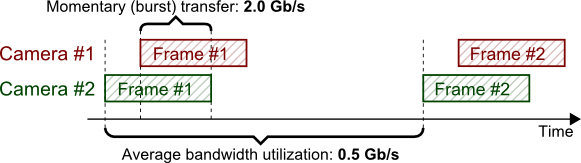
Although diagnostic tools will report network throughput utilization to be well below system limits it is still possible for short burst transfers to temporary exceed the system limits resulting in packets drop. To overcome such problems it is required to not only ensure camera framerates to be below proper limit, but also to limit the maximum network transfer speed of the device network adapters. Refer to the device documentation for details about how to limit the network transfer speed in specific device. Usually this can be achieved by decreasing value of parameters such as DeviceLinkThroughputLimit or StreamBytesPerSecond (in bytes per second), or by introducing delays in between the network packets by increasing parameters such as PacketDelay, InterPacketDelay or GevSCPD (measured in internal device timer ticks - must be calculated individually for device using device timer frequency).
Above requirements are especially important when cameras are connected to the computer using a single network card and a shared network switch:
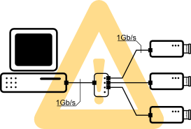
Special care must be taken to assure that all the cameras connected to the switch (when all transmitting at once) do not exceed transfer limits of the connection between the switch and the computer, both average transfer (by limiting the framerate) as well as temporary burst transfer (by limiting network transfer speed). Network switch will attempt to handle burst transfers by storing the packets in its internal buffer and transmitting packets stored in the buffer after the burst, but when the amount of data in burst transfer exceeds the buffer size the network packets will be dropped. Thus it is required for the switch buffer to be large enough to store all camera frames captured at once, or to limit transmission speed for the switch buffer to not overflow.
It is important to note that the maximum performance of the multi-camera system with shared network switch is limited by the throughput of the link between the switch and the computer, and usually it will not be possible to achieve the maximum framerate and/or resolution of the cameras.
A common case of using multiple cameras at once is to capture multiple photos of a object from a single trigger source (with synchronous triggering):
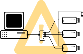
All above recommendations must be considered for such configuration. Because under synchronous triggering all the cameras will always be transferring images at the same time the problem of momentary burst transfer is especially present. Care must be taken to limit the maximum network transmission speed in the cameras to the system limits and to give enough time between trigger events for the cameras to finish the transfer.
| Previous: Working with GigE Vision® Devices | Next: GigE Vision Device Manager |