You are here: Start » Programming Reference » Array Synchronization
Array Synchronization
Introduction
In many applications several objects are analyzed on a single image. Most typically, in one of the first steps the objects are extracted (e.g. as an array of blobs, edges or occurrences of a template) and then some attributes are computed for all of them. In FabImage Studio these data items are represented as several synchronized arrays, with different arrays representing the objects and the individual attributes.
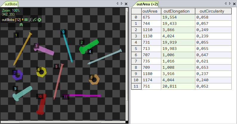
The elements of synchronized arrays correspond one-to-one with each other like the elements of consecutive rows of a table in numerical spreadsheet applications. Indeed, also in FabImage Studio synchronized arrays of numerical values can be presented as a table, whereas the corresponding graphical objects can be displayed with the corresponding indexes (after checking an appropriate option in the image view menu), that indicate which row they belong to:

Preview of several synchronized arrays.
Synchronized Inputs
Some filters have several array inputs and require that all the connected arrays are synchronized, so that it is possible to process the elements in parallel. For example, the SortArray filter requires that the array of the objects being sorted and the array of the associated values (defining the requested order) are synchronized. This requirement is visualized with blue semicircles on the below picture:

Visualization of inputs that require synchronized arrays.
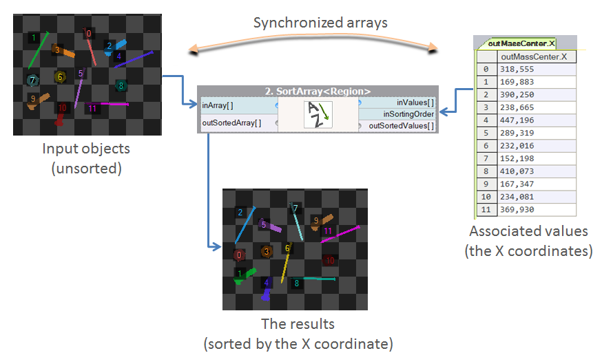
For example, we can use the SortArray filter to sort regions by the X coordinates of their mass centers:

The principle of synchronized inputs on the example of SortArray.
Other examples of notable filters that require synchronized input arrays include: GetMaximumElement, ClassifyByRange and DrawStrings_SingleColor (the arrays of strings and the corresponding center points must be synchronized).
Static Program Analysis
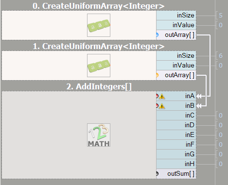
FabImage Studio performs a static program analysis to detect cases when arrays of possibly different sizes (unsynchronized) are used. If such a case is found, the user is warned about it before the program is executed and the detected issues are marked in the Program Editor with exclamation icons and red semicircles:

Visualization of an array synchronization problem.
Sometimes, for complicated programs, the static analysis mechanism may generate false warnings. In such cases, the user can manually mark the inputs as synchronized with the "Mark Arrays as Synchronized" command in the filter's input context menu.
Visualization of Related Arrays
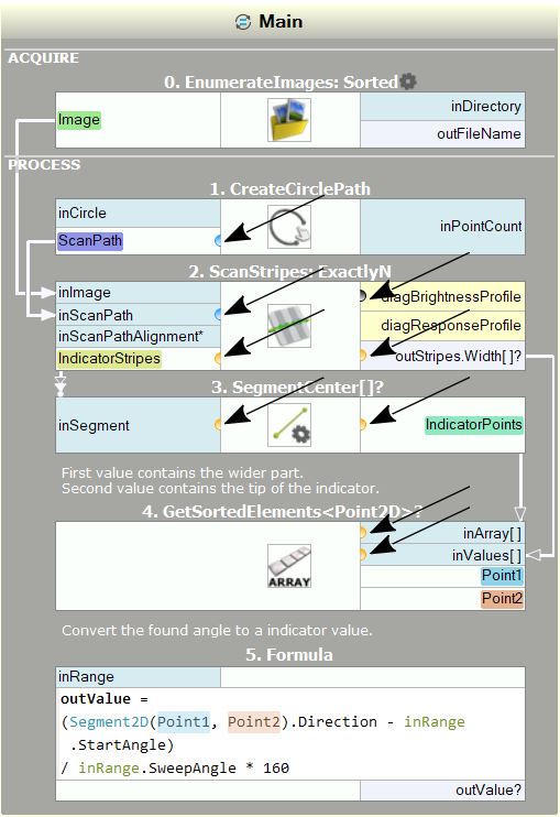
The next picture presents a complete visualization of array synchronization in a real program (the "Meter" official example). There are two colors of the semicircles – blue and yellow. By visualizing the array synchronization it is easy to see, which ports contain arrays describing the same entities. In this particular case the blue semicircles are related to the circular scanning path and the yellow circles are related to the founded stripes.

Visualization of example array synchronization.
Note: Array synchronization analysis and its visualization is turned on by default, but this can be turned off in the settings of FabImage Studio.
| Previous: Arrays | Next: Optional Inputs |

