
You are here: Start » Filter Reference » Computer Vision » Shape Fitting » FitSegmentToStripe
 Basic
Basic| Module: | MetrologyPro |
|---|
Performs a series of 1D stripe detections and finds a segment that best matches the detected points.
Applications
| Name | Type | Range | Description | |
|---|---|---|---|---|
 |
inImage | Image | Image to fit segment to | |
|
inFittingField | SegmentFittingField | Segment fitting field | |
|
inFittingFieldAlignment | CoordinateSystem2D* | Adjusts the fitting field to the position of the inspected object | |
|
inScanCount | Integer | 3 -  |
The number of points that will be searched to estimate the position of the segment |
|
inScanWidth | Integer | 1 - |
The width of each scan field (in pixels) |
|
inSamplingParams | SamplingParams | Parameters controlling the sampling process | |
|
inStripeScanParams | StripeScanParams | Parameters controlling the stripe extraction process | |
|
inStripeSelection | Selection | Selection mode of stripe | |
|
inLocalBlindness | LocalBlindness* | Defines conditions in which weaker edges can be detected in the vicinity of stronger edges | |
|
inMaxIncompleteness | Real | 0.0 - 0.999 | Maximal fraction of stripe points not found |
|
inOutlierSuppression | LineMEstimator* | Selects a method for ignoring incorrectly detected points | |
 |
outSegment | Segment2D? | Fitted segment in the middle of found stripe | |
|
outLeftSegment | Segment2D? | Fitted left segment | |
|
outRightSegment | Segment2D? | Fitted right segment | |
|
outStripes | Stripe1D?Array | Found stripes | |
|
outStripePoints | Point2DArray | Extracted points of middle segment of an image stripe | |
|
outDeviationProfile | Profile? | Profile of distances between the actual segment points and the corresponding reference segment points | |
|
outAlignedFittingField | SegmentFittingField | Fitting field used; in the image coordinate system | |
|
outBrightnessProfiles | ProfileArray | Extracted image profiles | |
|
outResponseProfiles | ProfileArray | Profiles of the edge (derivative) operator response | |
 |
diagScanSegments | Segment2DArray | Segments along which the scans were run | |
|
diagSamplingAreas | Rectangle2DArray | Areas from which the input image is sampled | |
Description
The operation tries to fit a given segment to stripe present in the inImage image. Internally, it performs a series of scans with the ScanSingleStripe filter along inScanCount specific scan segments which length is always equal to the inFittingField width and cannot be less than 4. The found points are then used to determine the actual position of the segment in the image. Only inMaxIncompleteness fraction of these scans may fail. If the fitting according to the given parameters is not possible, outSegment is set to Nil.
Hints
- Connect an input image to the inImage input.
- If the object location is variable, connect inFittingFieldAlignment to an appropriate local coordinate system (e.g. from a template matching filter).
- Define the inFittingField input to specify the area in which stripe scanning will be performed.
- Define inStripeScanParams.StripePolarity to detect a particular stripe type, and only that type.
- Adjust inStripeScanParams.MinStripeWidth and inStripeScanParams.MaxStripeWidth to the expected thickness of the stripe (in pixels).
- If the noise level is high, try increasing inScanWidth and/or inStripeScanParams.SmoothingStdDev.
- If no or too few stripe points are found, try decreasing inStripeScanParams.MinMagnitude.
- If some of the scans may fail, set the inMaxIncompleteness input accordingly.
- If some of the scans may produce false results, try different values of the inOutlierSuppression input.
- Use the diagScanSegments and outStripePoints outputs to visualize the scanning results.
Examples
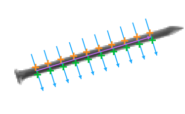
Fitting a segment to the dark stripe of a nail
(inStripeScanParams.Polarity = Dark).
Remarks
Read more about Local Coordinate Systems in Machine Vision Guide: Local Coordinate Systems.
This filter is a part of the Shape Fitting toolset. To read more about this technique, one can refer to the Shape Fitting chapter of our Machine Vision Guide
Hardware Acceleration
This operation supports automatic parallelization for multicore and multiprocessor systems.
Complexity Level
This filter is available on Basic Complexity Level.
Filter Group
This filter is member of FitSegment filter group.
See Also
- FitSegmentToEdges – Performs a series of 1D edge detections and finds a segment that best matches the detected points.
- FitSegmentToRidges – Performs a series of 1D ridge detections and finds a segment that best matches the detected points.