
You are here: Start » Filter Reference » Computer Vision » Camera Calibration » CalibrateWorldPlane_OffgridOrigin
 Expert
| Module: | Calibration |
|---|
Finds the image to world plane transformation matrix, with world origin and axes specified in the image coordinates.
Applications
| Name | Type | Range | Description | |
|---|---|---|---|---|
 |
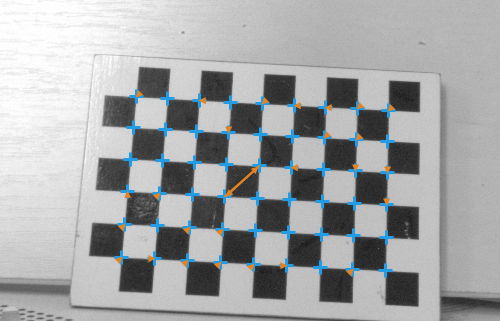
inImageGrid | AnnotatedPoint2DArray | Annotated calibration grid | |
|
inCameraModel | AnyCameraModel* | For undistortion of inImageGrid. If not supplied, the filter will assume that grid came from undistorted image. | |
|
inGridSpacing | Real | 0.000001 -  |
Real-world distance between adjacent grid points. |
|
inGridThickness | Real | The world plane will be shifted by given amount in direction perpendicular to the grid to compensate for grid thickness. Note, that inWorldPlaneOrigin and inWorldPlaneXAxis won't be compensated, so they need to be selected on the target world plane, and not on the grid. | |
|
inWorldPlaneOrigin | Point2D* | Sets world plane origin (as the image point). The world plane origin will lie at the specified image point. Note, that this point won't be shifted by inGridThickness parameter. | |
|
inWorldPlaneXAxis | Point2D* | Sets world plane x axis direction (as the image point). The world plane x axis will lie at the specified image point. Note, that this point won't be shifted by inGridThickness parameter. | |
 |
outTransform | RectificationTransform | ||
|
outRmsError | Real | RMS reprojection error, in pixels. | |
|
outMaxReprojectionError | Real | Maximum reprojection error, in pixels. | |
|
outReprojectionErrorSegments | Segment2DArray | Array of segments connecting input image points to grid reprojections. | |
Description
The filter estimates the correspondence between the image plane and a "world plane" – a given planar surface in observed space. The image plane, and thus inImageGrid points are assumed to be distorted, and to correct for the distortion the inCameraModel (calibration data) needs to be provided. The calculated result – outTransform contains all the information for transforming the distorted image plane to the world plane.
The inCameraModel is also used to define the type of the planar correspondence. For a standard projective camera (pinhole camera), the planar correspondence is a homography. If the inCameraModel is a telecentric camera, the planar correspondence is affine (as there are no perspective parameters in orthographic projection). If no inCameraModel is provided, the filter defaults to homography.
The homography requires at least four inImageGrid points. The affine relation requires at least three.
This filter allows for setting the world plane origin and x-axis direction in terms of input image points - see the inWorldPlaneOrigin and inWorldPlaneXAxis. Note that the origin and the axis direction does not need to lie on a grid point, it can be arbitrarily chosen.
The filter provides a few methods for judging the feasibility of calculated solution.
- The outRmsError and outMaxReprojectionError. The main contributor to these values is the random noise in inImageGrid point positions. Model mismatch (i.e. trying to calibrate a non-planar object, e.g. wavy surface) will also result in increased reprojection errors. Large difference between outRmsError and outMaxReprojectionError could be a sign of presence of outliers in input data.
- The outReprojectionErrorSegments consists of segments connecting input image points to reprojected world points, and thus it can be readily used for visualization of per-point reprojection errors.
Hints
- Image to world plane coordinate transform can be obtained from as few as 4 point correspondences, however high accuracy calculations need a considerable amount of high quality calibration points. The calibration plane should contain about hundred points, spanning whole area of interest. Take care of proper conditions when taking the calibration images: reduce vibrations that may yield motion blur, prevent reflections from the calibration surface (ideally use diffusion lighting).
Examples

Good case of image to world plane calibration using high amount of calibration points. Calibration resulted in RMS and maximum reprojection errors less than 1.0, as expected. The outReprojectionErrorSegments are not visible at that scale.
Example of a gross error. The RMS reprojection error is 17.6, max reprojection error is 91.2, source of these errors is clearly visible thanks to outReprojectionErrorSegments: the association of image points and their grid coordinates in inImageGrid is wrong.
Errors
This filter can throw an exception to report error. Read how to deal with errors in Error Handling.
List of possible exceptions:
| Error type | Description |
|---|---|
| DomainError | inGridSpacing needs to be positive |
Complexity Level
This filter is available on Expert Complexity Level.
Filter Group
This filter is member of CalibrateWorldPlane filter group.
See Also
- CalibrateWorldPlane_Default – Finds the image to world plane transformation parameters from world plane calibration grid. World plane origin and axes are unspecified.
- CalibrateWorldPlane_Labeled – Finds the image to world plane transformation parameters using sparse world coordinate information, i.e. world coordinates are known for only a few points of the grid.
- CalibrateWorldPlane_Multigrid – Finds the image to world plane transformation parameters using multiple grids, using sparse world coordinate information.
- CalibrateWorldPlane_Manual – Finds the image to world plane transformation parameters. Image and their corresponding world points are directly specified (no grid needed).
- CalibrateCamera_Pinhole – Finds the camera intrinsic parameters from calibration grids. Uses pinhole camera model (perspective camera).
- CalibrateCamera_Telecentric – Finds the telecentric camera intrinsic parameters from calibration grids.
- ImagePointsToWorldPlane – Finds the world coordinates of image Points.
- WorldPlanePointsToImage – Finds the image coordinates of world plane Points.
- CreateRectificationMap_PixelUnits – Computes a spatial map for transforming distorted images to rectified images defined in world coordinate plane. Defines the output geometry in pixels.
- CreateRectificationMap_WorldUnits – Computes a spatial map for transforming distorted images to rectified images defined in world coordinate plane. Defines the output geometry in world units.