
You are here: Start » Program Examples » Cap (Easy)
Cap (Easy)
Aim:
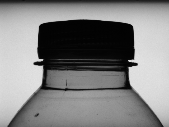
The task of this example is to check whether a seal (plastic ring under the cap) is correctly placed.
Input:
An image of the top of a bottle. The position of the bottle is variable.
Output:
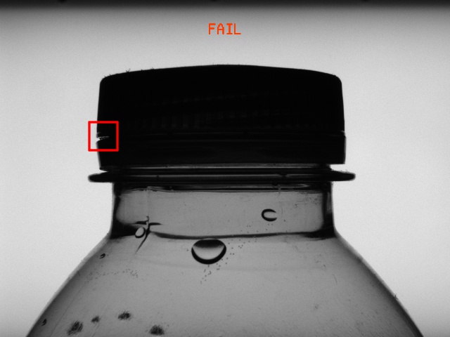
The result of the inspection printed on the image. If a defect is detected, a rectangle is drawn around it.
Hints:
This is an easier variant of the same example "Caps (Advanced)". If you are more advanced level in programming in FabImage Studio, please refer to that example. If you are new to FabImage Studio, then carry on here.
The first step to perform required inspection is the detection of the position of an object in an image. As the bottle moves particularly along the X axis and the background is consistent, the best way is applying the 1D Edge Detection technique and creating a local coordinate system based on a detected edge.
Labeling connections is explained in this article.
Solution (FIS):
-
In Workspace Explorer, open the workspace Examples, and in the Filmstrip window, select the CapEasy dataset. Drag the Image channel to the ACQUIRE section.
-
Add the ScanSingleEdge filter. Connect the outImage output of the ReadFilmstrip to the inImage.
-
Click on the ScanSingleEdge filter. In the Properties window in the bottom left corner, choose the inScanPath and define the scanning path, so that it can find the left edge of the cap. Set the inEdgeScanParams.MinMagnitude to 10 to ensure edges are resistant to possible noise.
-
Add the CreateCoordinateSystemFromPoint filter. Connect the outEdge.Point to the inPoint. It will create a local coordinate system at the point where the edge has been found.
-
Add another ScanSingleEdge filter. Connect the outImage output of the ReadFilmstrip to the inImage, and connect the outCoordinateSystem to the inScanPathAlignment.
-
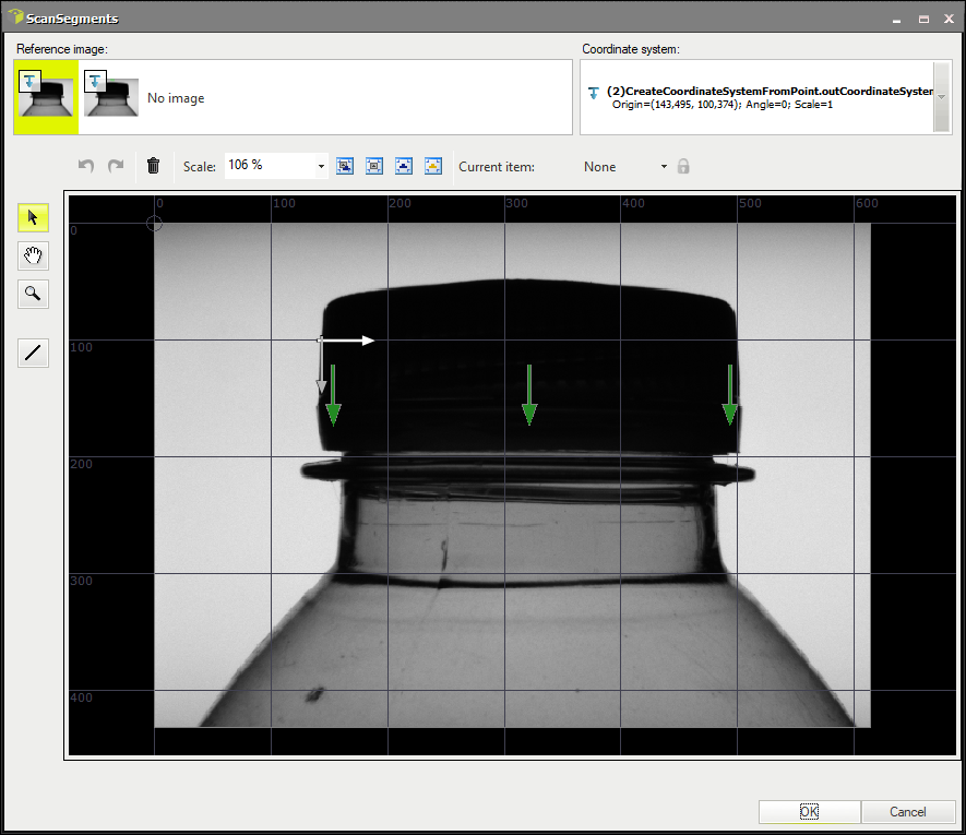
Now go to the Project Explorer (the left side of FabImage Studio). Create a new global parameter. Name it ScanSegments of the Segment2DArray type. Then, define three scanning paths as shown in the image below:
 Connect the ScanSegments to the inScanPath. This filter will now be executed in an array mode.
 -
Click on the ScanSingleEdge filter and in the Properties window make the following changes:
- Set the inScanWidth to 70 so that the width of the scanning path is wide enough,
- Set the inEdgeScanParams.MinMagnitude to 4 to find even the smallest deviations on the seal,
- Set the inEdgeScanParams.EdgeTransition to DarkToBright.
-
Use Show/Hide ports option to add the outEdge.IsNil output. Label it as DefectPresent.
-
Add a new formula. Use label DefectPresent in the statement without connecting it to the filter:
outIsOK = all(DefectPresent) ?? False
-
Now create a new step macrofilter, name it DrawResults and connect the following inputs to it:
- the outImage output of the ReadFilmstrip as inImage,
- the outEdge.Point (from the latter filter) as inDefectLocations,
- the Formula's outIsOK output as inIsOK.
-
Step inside the newly-created macrofilter. Add the ChooseByPredicate of the String type. In the Properties window set following values:
- PASS in the inObjectIfTrue,
- FAIL in the inObjectIfFalse.
-
Connect the macrofilter's input inIsOK to the inCondition.
-
Add the DrawStrings_MultiColor filter:
- Connect the macrofilter's input inImage to the inImage,
- Connect the outObject to the inStrings,
- Connect the macrofilter's input inIsOK to the inColorIds,
- Define the location of the text in the inLocations somewhere over the cap,
- Set the inPalette to red at index 0 and green at 1,
- Set the inSize to 24.
-
Add the CreateBox filter:
- Connect the macrofilter's input inDefectLocations to the inLocation,
- Set the inLocationAnchor to MiddleCenter,
- Set the inWidth to 40,
- Set the inHeight to 40.
-
Add the DrawRectangles_SingleColor filter:
- Connect the outImage to the inImage,
- Connect the outBox to the inRectangles,
- Set the inColor to red,
- Set the inDrawingStyle.Thickness to 3,
- Connect the outImage to the macrofilter outputs as outImage.
Macrofilter Main

Macrofilter DrawResults

Used Filters
| Icon | Name | Description |
|---|---|---|
| ChooseByPredicate | E.g. to choose GREEN color to visualize correct objects or RED to visualize defective ones. | |
| CreateBox | Creates a box. | |
| CreateCoordinateSystemFromPoint | Most often used to define an object alignment from results of 1D Edge Detection or Blob Analysis. | |
| DrawRectangles_SingleColor | Draws rectangles on an image with a single color. | |
| DrawStrings_MultiColor | Draws strings (text) on an image with multiple colors. | |
| ScanSingleEdge | Very fast detection of an object (e.g. horizontal displacement of a bottle) and simple measurements (e.g. liquid level in a bottle). |
Further Readings
- 1D Edge Detection - The article explaining how edge detection filters work.
- Local Coordinate Systems - This article describes basic concept of using the coordinate systems.