You are here: Start » Program Examples » Calibration with filters on remapped image
Calibration with filters on remapped image
Aim:
The goal is to compute the world coordinates based on provided images of the calibration grid. The application uses filters instead of the editor.
Input:
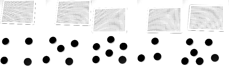
A few images of the calibration grid and a board with circles.
Output:
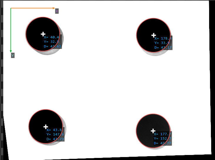
The coordinates of the found dots.
Hints:
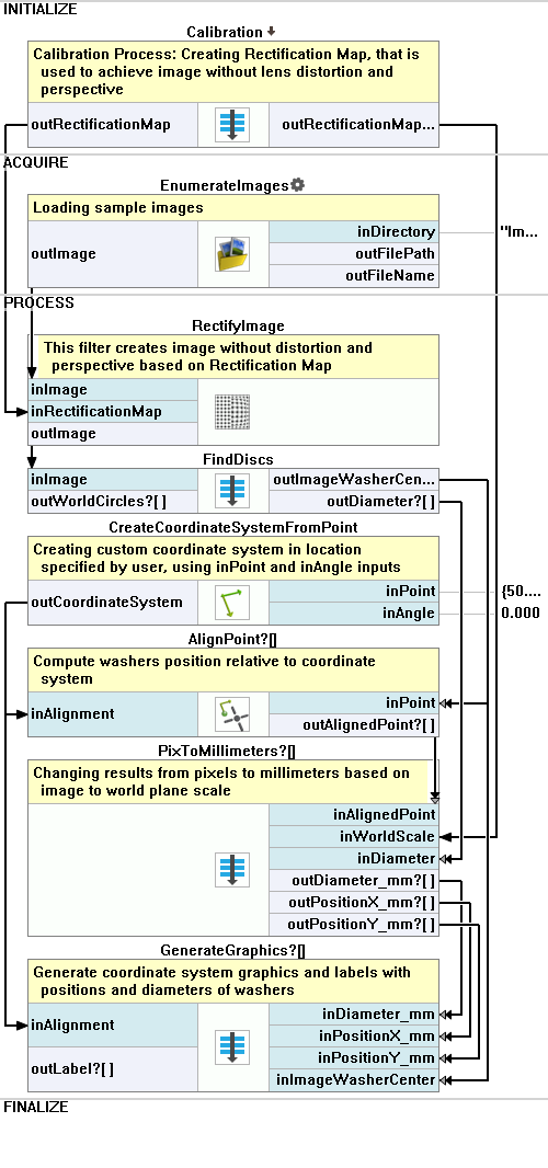
First of all, as there are both lens and perspective distortion, they need to be removed by using the RectifyImage filter. Next, to correctly locate the dots, it is best to use the ExtractBlobs_Intensity. Eventually, to find the center points of circles, try fitting a corresponding shape to them and use an appropriate property output.
Solution (FIS):
-
In the INITIALIZE section, create a Step macrofilter and name it Calibration.
-
Inside the Calibration macrofilter, create a Task macrofilter and name it FindCameraCalibrationGrids. Create a new input of the Task of type Directory. Set its value to the directory to the Calibration Grid images.
-
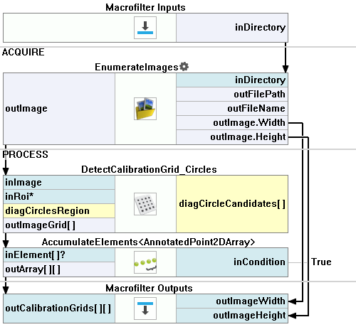
Inside the FindCameraCalibrationGrids macrofilter:
- Add the EnumerateImages and connect the inDirectory with the macrofilter input. Drag the outImage.Width and theoutImage.Height outputs to the Macrofilter Outputs section.
- Add the DetectCalibrationGrid_Circles filter and connect its inImage input to the EnumerateImages outImage output. Set the inCircleRadius to 11.
- Add the AccumulateElements filter, connect its input with the DetectCalibrationGrid_Circles output. Drag the output to the Macrofilter Outputs section and name the new macrofilter output CalibrationGrids.
-
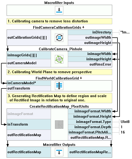
Return to the Calibration macrofilter. Add the CalibrateCamera_Pinhole filter. Connect its inputs with the FindCameraCalibrationGrids outputs.
-
Create a new Step macrofilter named FindWorldCalibrationGrid. Drag the outCameraModel output of the previous filter to the new Step to create the input.
-
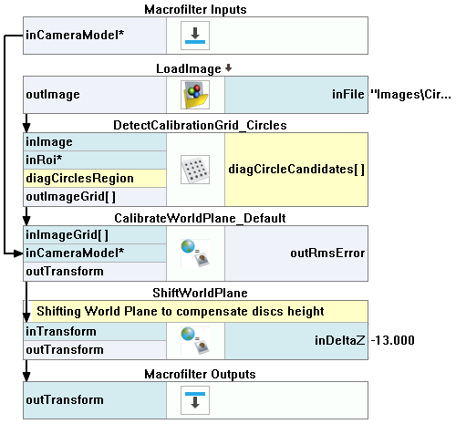
Inside the FindWorldCalibrationGrid macrofilter:
- Add the LoadImage and specify the directory of the first Calibration Grid image in the inFile.
- Add the DetectCalibrationGrid_Circles filter and connect its inImage input to the previous filter's output. Set the inCircleRadius to 8.
- Add the CalibrateWorldPlane_Default filter. Connect its inImageGrid input to the output of the previous filter and the inCameraModel input to the macrofilter's input. Set the inGridSpacing to 7 and the inGridThickness to 6.
- Add the ShiftWorldPlane filter, connect its inTransform input with the CalibrateWorldPlane_Default outTransform output. Set the inDeltaZ to -13. Drag the outTransform to the Macrofilter Outputs section.
-
Return to the Calibration macrofilter. Add the CreateRectificationMap_PixelUnits filter:
- For the inImageFormat input, connect the Width and the Height to the Width and the Height outputs of the FindCameraCalibrationGrids macrofilter.
- Connect the inTransform input to the FindWorldCalibrationGrid output.
- Drag the outRectificationMap and the outRectificationMap.RectifiedWorldScale outputs to the Macrofilter Outputs section.
-
Return to the Main macrofilter. Add the EnumerateImages and specify the directory of images in the inDirectory.
-
Add the RectifyImage filter. Connect the outImage to the inImage. Connect the inRectificationMap input to the RectificationMap output of the Calibration macrofilter.
-
Create a new Step macrofilter named FindDiscs. Drag the RectifyImage outImage output to the new macrofilter to create the input.
-
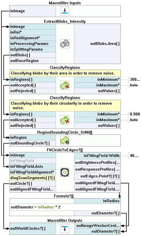
Go to the FindDiscs macrofilter. Add the ExtractBlobs_Intensity filter. Connect its inImage input to the macrofilter's input.
-
Add 2 ClassifyRegions filters:
- For the first one, connect the inRegions input to the ExtractBlobs_Intensity outBlobs output and set the inMinimum to 30000.
- For the second one, connect the inRegions input to the outAccepted output of the previous filter. Set the inFeature to Circularity_BoundingCirclePreserving and the inMinimum to 0.9.
-
Add the RegionBoundingCircle_OrNil filter and connect its input to the last ClassifyRegions outAccepted output.
-
Add the FitCircleToEdges filter:
- Connect the inImage input to the macrofilter's input.
- For the inFittingField, connect the Axis to the RegionBoundingCircle_OrNil output and set the Width to 40.
- Expand the outputs to get the outAlignedFittingField Axis.Radius value.
- Drag the outAlignedFittingField Axis output to the Macrofilter Outputs section and name the new output ImageWasherCenter.
- Drag the outCircle output to the Macrofilter Outputs section and name the new output WorldCircles.
-
Add a formula. Drag the outAlignedFittingField Axis.Radius output from the previous filter to create the input and name it Radius.
outDiameter = inRadius * 2
-
Drag the formula output to the Macrofilter Outputs section.
-
Go back to the Main macrofilter. Add the CreateCoordinateSystemFromPoint filter. Set the inPoint input as {50;50}.
-
Add the AlignPoint filter. Connect its inAlignment input to the CreateCoordinateSystemFromPoint output and the inPoint input to the ImageWasherCenter output of the FindDiscs macrofilter.
-
Create a new Step macrofilter named PixToMillimeters. Drag to it:
- the AlignPoint output
- the Calibration macrofilter RectificationMapRectifiedWorldScale output and name the new input WorldScale
- the Diameter output of the FindDiscs macrofilter.
-
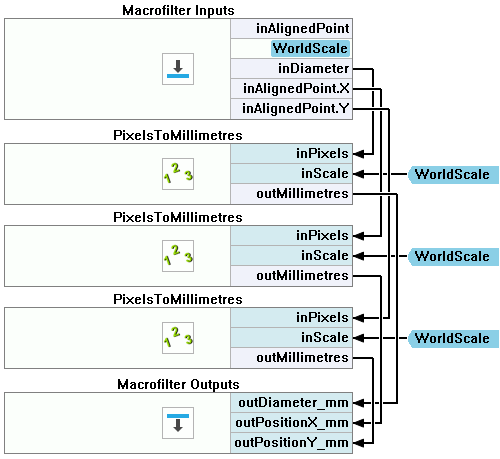
Inside the PixToMillimeters macrofilter:
- Label the WorldScale input.
- Expand the AlignedPoint input to get X and Y values separately.
- Add 3 PixelsToMillimetres filters:
- Connect each PixelsToMillimetres outputs to the macrofilter's output and name them: Diameter_mm, PositionX_mm and PositionY_mm.
-
Go back to the Main macrofilter. Create a new Step macrofilter named GenerateGraphics. Drag to it:
- all the PixToMillimeters macrofilter outputs
- the CreateCoordinateSystemFromPoint filter output
- the ImageWasherCenter output of the FindDiscs macrofilter.
-
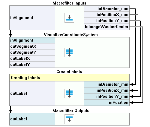
Inside the GenerateGraphics create 2 Step macrofilters and name them VisualizeCoordinateSystem and CreateLabels. Drag the Alignment macrofilter input to the VisualizeCoordinateSystem step and all the rest of the inputs to the CreateLabels.
-
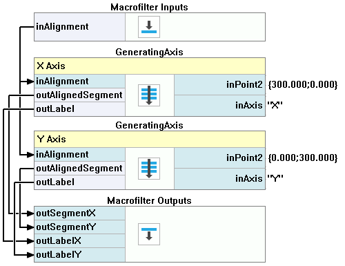
Inside the VisualizeCoordinateSystem macrofilter, create a new Step macrofilter. Name it GeneratingAxis. Create 3 inputs of it:
- the Alignment of the CoordinateSystem2D type
- the Point2 of the Point2D type
- the Axis of the String type
-
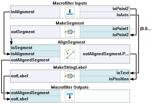
Inside the GeneratingAxis macrofilter:
- Add the MakeSegment filter. Connect the inPoint2 input to the macrofilter's Point2 input.
- Add the AlignSegment filter. Connect the inSegment input to the previous filter's output. Connect the inAlignment input to the macrofilter's Alignment input. Expand the outputs to get the outAlignedSegment Point2 value. Drag the outAlignedSegment output to the Macrofilter Outputs section.
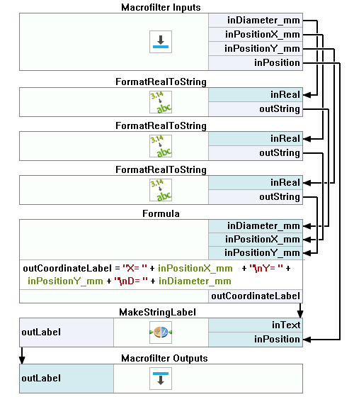
- Add the MakeStringLabel filter. Connect the inText input to the macrofilter's Axis input. Connect the inPosition input to the Point2 output of the previous filter. Drag the outLabel output to the Macrofilter Outputs section to create a new output.
Macrofilter Main.
Macrofilter Calibration.
Macrofilter CreateLabels.
Macrofilter FindCameraCalibrationGrids.
Macrofilter FindDiscs.
Macrofilter FindWorldCalibrationGrid.
Macrofilter GenerateGraphics.
Macrofilter GeneratingAxis.
Macrofilter PixToMillimeters.
Macrofilter VisualizeCoordinateSystem.