You are here: Start » Application Notes » Using TCP/IP Communication
Using TCP/IP Communication
Purpose and equipment
This document describes how to a make practical example of TCP/IP communication between FabImage Studio and a PLC device. For this case FabImage Studio 4.11 and Simatic S7- 1200 CPU 1212C AC/DC/RLY with TIA Portal V15 have been used. For more theory you can check out TCP/IP Communication article.
Required equipment:
- SIMATIC S7-1200 controller or other from SIMATIC S7 family
- TIA Portal V15
- FabImage Studio 4.11 Professional or later
Overview and first steps
In this example, you will create an application which sends a number from FabImage Studio to a PLC and receives the square of this value calculated by the PLC. The application will be configured as a master and the PLC as a slave.
First, you need to make a hardware connection between the PLC and the PC. Network configuration will be described in the next chapter.
Network configuration
Main network configuration
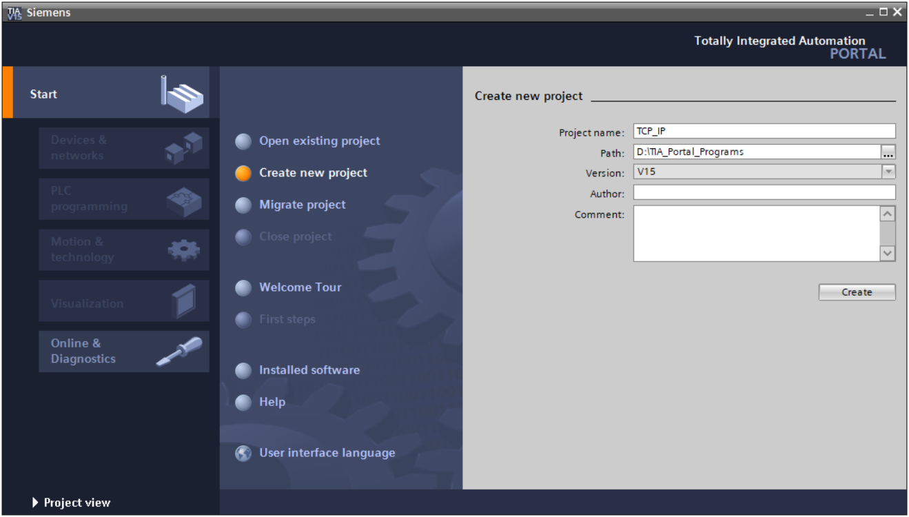
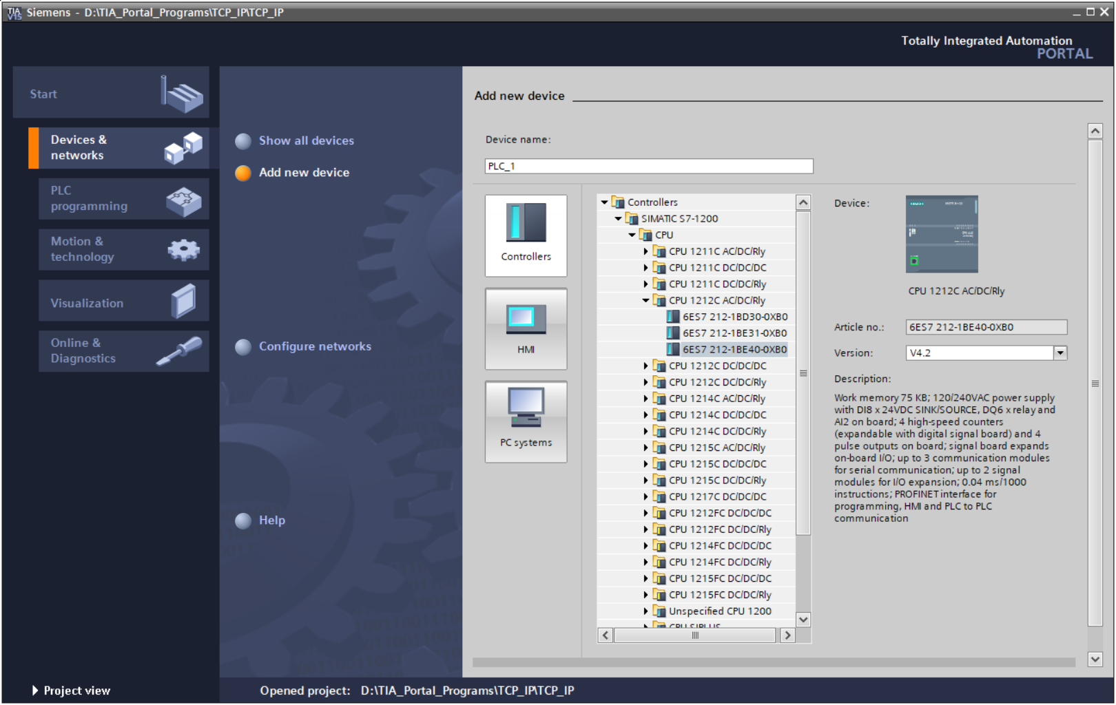
Create a new project in the TIA Portal environment and add your device by double-clicking on Add new device. Select your controller model, its CPU etc. in the list of controllers available in a dialog box. Click on OK button if you are ready.
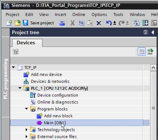
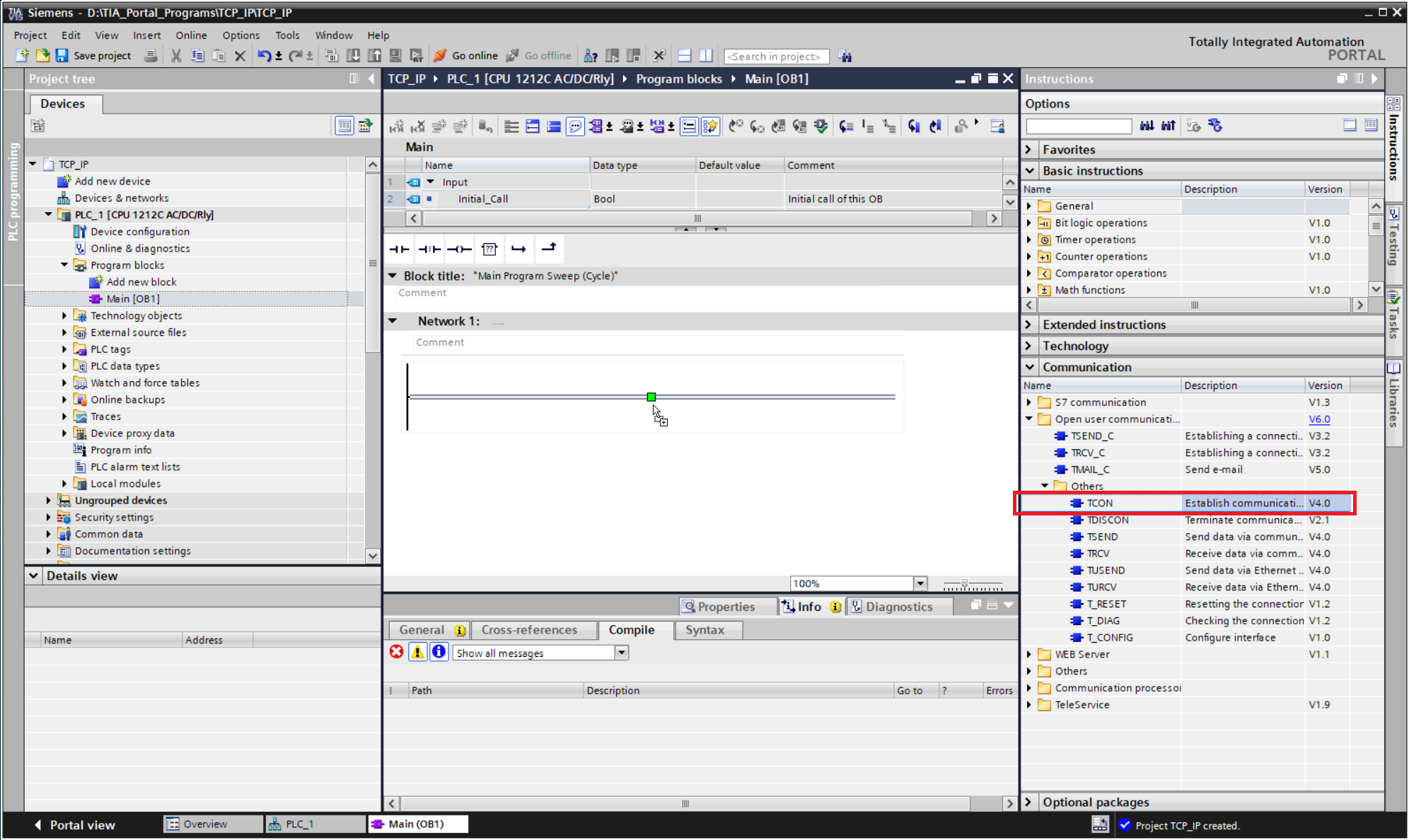
Expand a Program blocks list and double-click on the Main icon. Now you should see a network view. Find the Communication tab on the right side and double-click on the TCON icon available in Communication -> Open user communication -> Others.
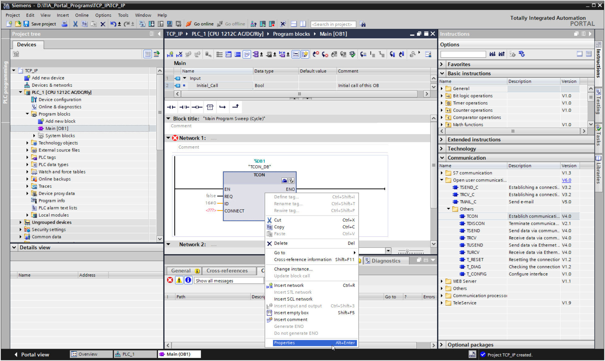
The TCON instruction is used for establishing the TCP communication. It is now visible in the Network View. Right-click on it and select Properties.
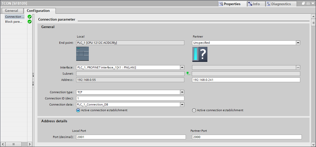
In the Configuration tab, you need to set the IP address of your PC. To check the IP address, you can use the Command Prompt and the ipconfig command. Other parameters should be set like in the next figure. If you use these settings, the IP of the PLC device should be set automatically. If you cannot establish the connection, please follow steps described in next chapter about troubleshooting.
Troubleshooting IP addressing
If you have not been able to properly set the IP address of the PC, as described in the previous chapter, you should set a static IP following steps described below or otherwise, feel free to skip this step.
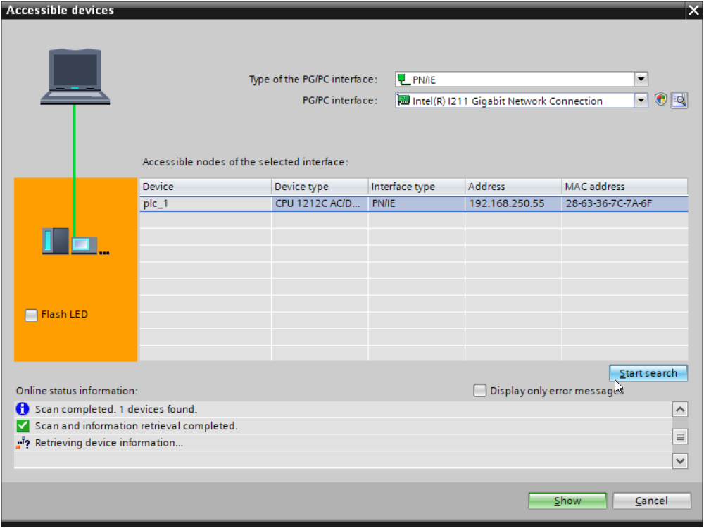
Choose Accessible devices from a toolbar to open the configuration window. Select PN/IE type of the PG/PC interface and select the Ethernet card connected to the PLC. Click the Start search button, choose your PLC from the list of accessible nodes and click on the Show button. You should get a new static IP which you can use in steps from the previous chapter.

Creating a PLC program
This chapter describes how to create a PLC program establishing TCP/IP communication.
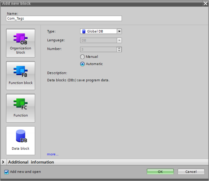
You should already have the TCON function block in the Network view. Now it is time to create a Variable Table by double-clicking on the Add new block in the Project Tree like it is shown here. Select the Data block (DB) and name the block as shown in the image below.
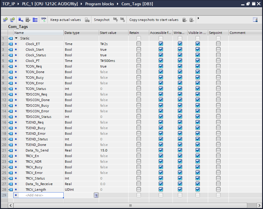
Now define variables in the Data block. Use the same names and data types as shown in the image below. If you want to create a new row, just right click on any row and select Insert row. Please note that setting the right values of Start Values is essential in this step.
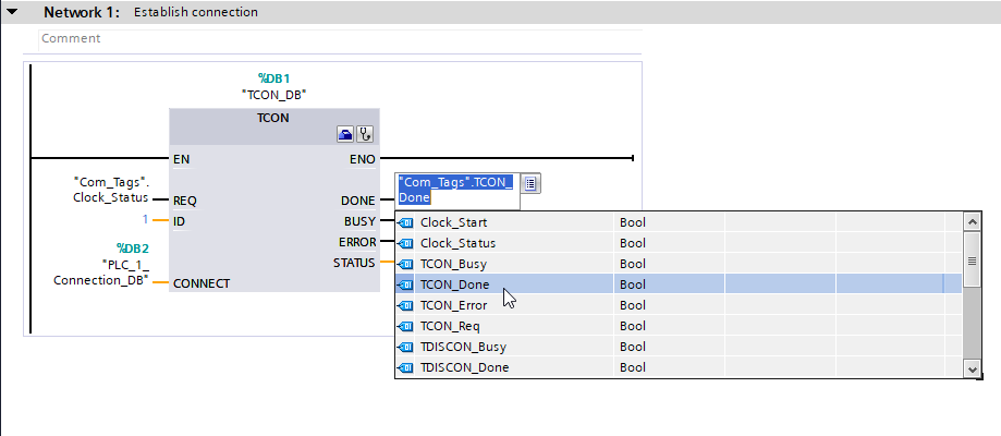
Label all the inputs and outputs of the TCON block in the network view. To label connection drag and drop variables from Data block to the Program block (for example TYCON) or double click on a connection and select displayed icon like in the image shown below.
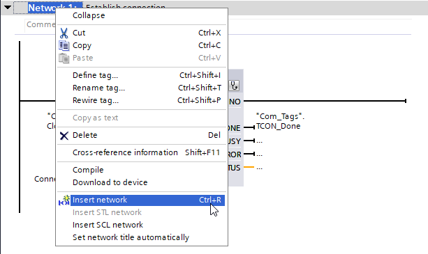
Add 5 networks to the Main program. In order to do that right-click on the existing network and select Insert network as shown in the image below:
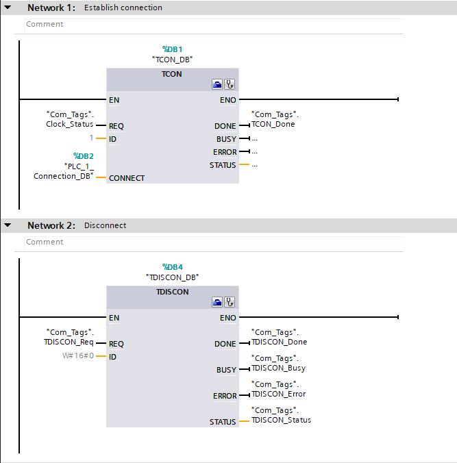
Insert additional communication block, TDISCON, from the Communication tab like on this previous picture. Label all connections as shown in the image below. TCON block will be used to establish TCP/IP connection while TDISCON will be used to close the connection.
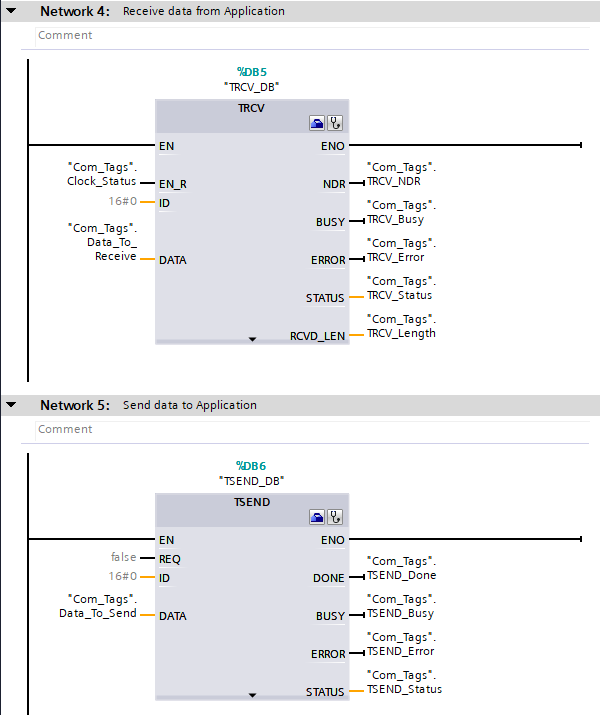
The next step is to allow exchanging data between FabImage Studio and PLC. Use TRCV block for receiving messages and TSEND block for sending messages to FabImage Studio. Label added blocks as shown in the image below:
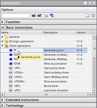
To start connection over TCP/IP using TCON you need to use rising edge signal on REQ input. Same applies to other function blocks (in TRCV a rising edge signal should be set on EN_R input). You can switch these values manually by right-clicking on the connection and selecting Modify. In this sample application, an automatic pulse generator will be used in order to avoid switching the values manually. Insert a new network and add a TP block located in the Basic instructions tab inside the Timer operation folder (picture below).
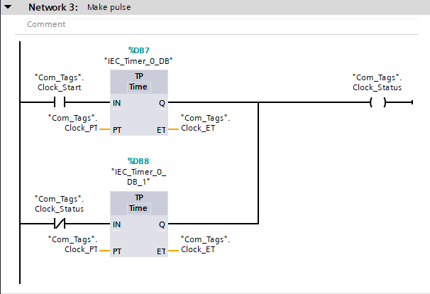
Use configuration from next picture to create a network which will be generating a proper signal.
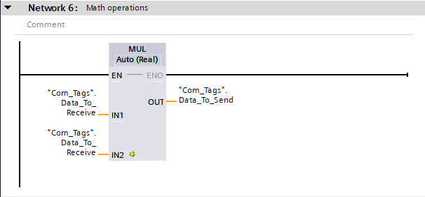
In the last step please add a sample math function e.g. multiplying. In this example a number received from FabImage Studio will be squared and the result calculated on the PLC's side will be sent back to FabImage Studio.
If all previous steps have been done correctly, your PLC program is ready. Compile the program and download it to the device. To see current states of variables, turn on Monitoring mode.


Creating application in FabImage Studio
In this chapter, the individual steps how to create an FabImage Studio application to communicate with a PLC over TCP/IP are described. Before proceeding to the next steps, make sure that all previous steps have been done correctly.
FabImage Studio provides a set of ready-to-use filters for communication over the TCP protocol. A full list of the filters is available here. To get more detailed information on how to work with TCP filters, please refer to our official example IO Simple TCPIP Communication and the article Using TCP/IP Communication in the FabImage Studio documentation.
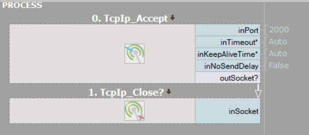
First of all, create a new project and add a TcpIp_Accept filter. This filter, as well as other TCP/IP filters, are available in the Program I/O category of a Toolbox. Please note that TcpIp_Accept filter accepts a connection from a remote client, so in this case the FabImage Studio program will be working as a server. If you want the program to work as a Client, the TcpIp_Connect filter should be used.
Set inPort value to 2000 to match configuration from PLC. Insert a TcpIp_Close filter below the TcpIp_Accept and connect the outSocket output with the inSocket input as shown in the image below. If the connection has been configured properly, you should be able to step over all steps in program.
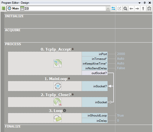
Create a new Task Macrofilter and create an inSocket input (you can do this by dragging the outSocket and dropping it on the macrofilter). Connect outSocket from TcpIp_Accept filter to the inSocket input of Task Macrofilter. In this example FabImage Studio will connect over TCP/IP only once and the connection will be held. The data exchange will be executed inside the Task Macrofilter.
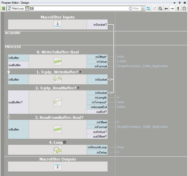
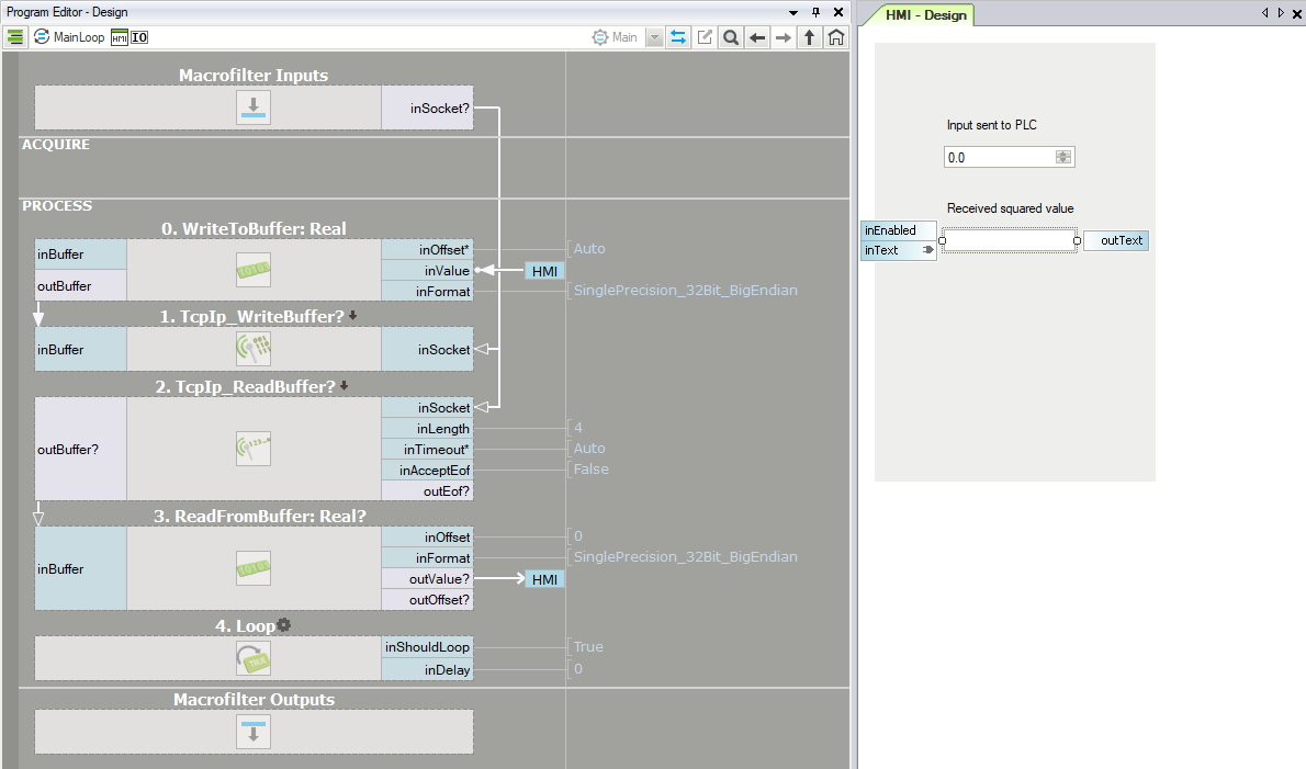
Inside the MainLoop macrofilter you need to add the TcpIp_WriteBuffer filter to send messages and TcpIp_ReadBuffer to receive messages over TCP/IP. PLC program works on Buffer data type, in our example user will be specifying decimal numbers, therefore conversion from Buffer to Real value is needed. To do so, use the WriteRealToBuffer and ReadRealFromBuffer filters which automatically convert decimal value into specified binary representation and write it to/read it from a buffer.
Add the Loop filter at the end of the algorithm inside MainLoop macrofilter. Make sure to set proper format - SinglePrecision_32Bit_BigEndian, otherwise program will not work properly. The algorithm should look like the one shown in the next picture.
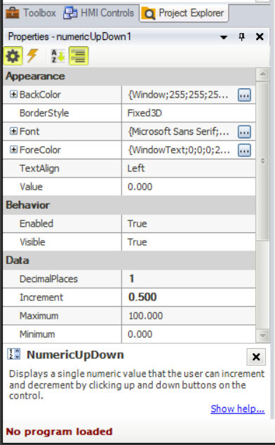
In the next step simple HMI will be created. Add a NumericUpDown and TextBox controls from the Controls tab. Connect NumericUpDown outValue output to the WriteRealToBuffer inValue input (previous picture) and the output outValue of ReadRealFromBuffer filter to the inText of the TextBox control. Set the properties of the NumericUpDown HMI control as shown in the next picture.
In the last step use Label control to describe the previously added controls. The current algorithm should look like the one shown in the next picture. The program can work in current state; however, it will be improved in next steps.
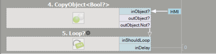
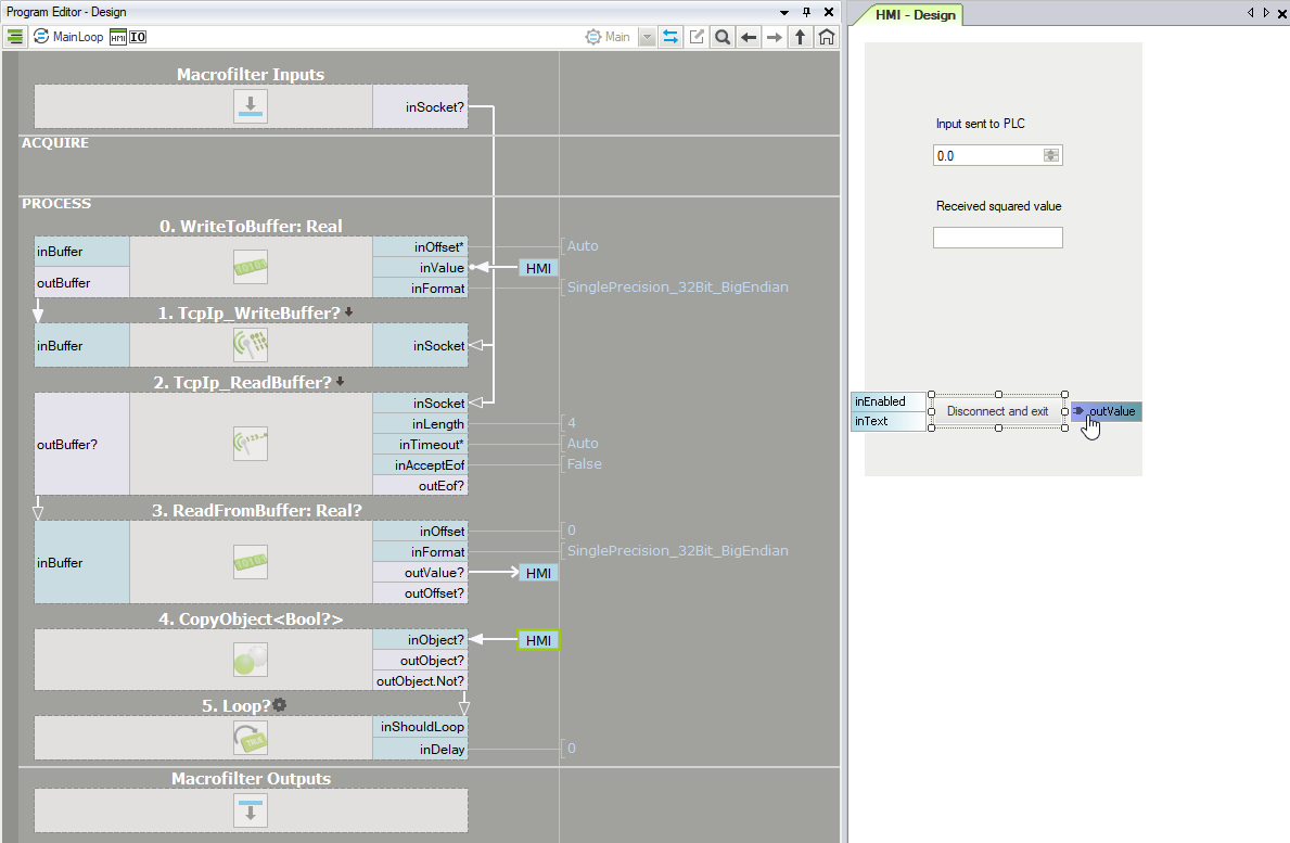
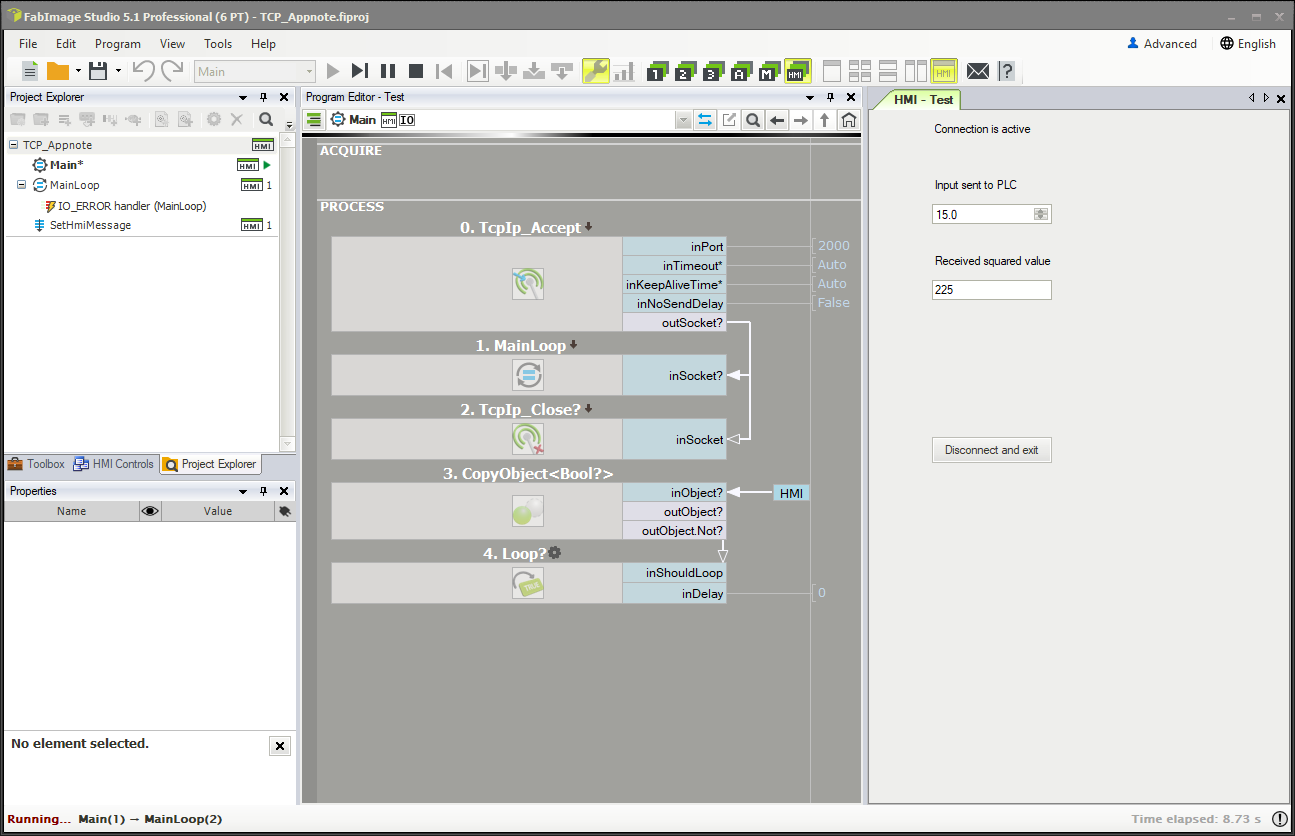
Main Loop is running continuously due to the inShouldLoop input of Loop, which is always true in the current structure. In order to change that, add ImpulseButton and name it "Disconnect and exit". Loop filter generates loop when true value is passed to the inShouldLoop input. Default state of ImpulseButton outValue output is false, so this value should be negated before connecting it to the Loop filter. Insert the CopyObject filter inside MainLoop macrofilter and set the Bool? data type. Connect ImpulseButton outValue to the inObject input of the CopyObject filter. Right click on the outObject output, select Property Output and Not variant. Now connect outObject.Not output to the inShouldLoop input as shown in the next picture.
The same ImpulseButton control will be used to Close TCP/IP connection in Main task. Use the structure known from description above and Figure 25 to control Loop filter in Main task as shown in the image below:
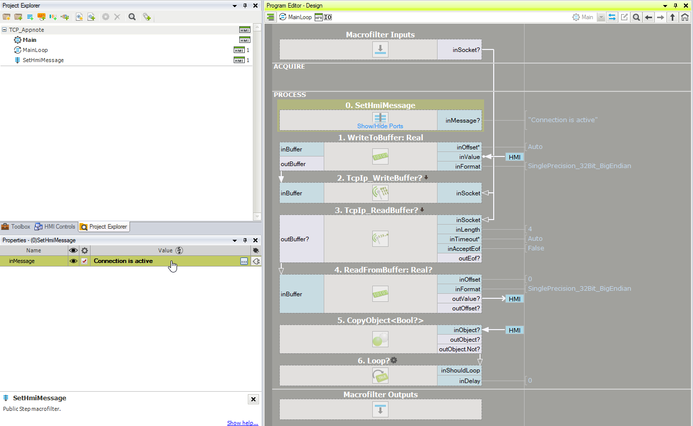
The application is almost ready, but every good and stable application should have Error handling. Next modification will allow you to see the current connection state, for example: wait for connection, connection is active, and lost connection. In order to do that, go inside MainLoop macrofilter, right click on the program editor window and insert a step macrofilter. Name new created macrofilter as "SetHmiMessage" and create new String? type input. Name the newly created input as inMessage. This macrofilter will be used in a few places is this application, in case you use it inside MainLoop macrofilter, insert command "Connection is active" in macrofilter properties as shown in image below:
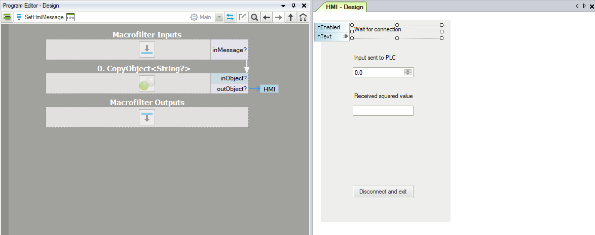
Enter SetHmiMessage macrofilter and add the CopyObject filter with String? type. Add a new Label control to the HMI window. As default text set "Wait for connection". Connect the outObjects output from CopyObject filter to the inText input of Label control. The result should look like in the image below:
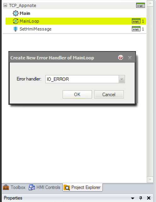
Currently, connection state message has two different variants: Wait for connection and Connection is active. Now, we are going to add message which will be prompted when connection is broken. In order to do that, you need to use Error handlers for MainLoop macrofilter. Right click on the MainLoop macrofilter, visible in the Project Explorer window, and select Add New Error Handler... Choose IO ERROR from the list, as shown in the next figure.
Enter newly created error handler and add SetHmiMessage macrofilter. Set inMessage? input to "Connection lost" as shown in the figure below:
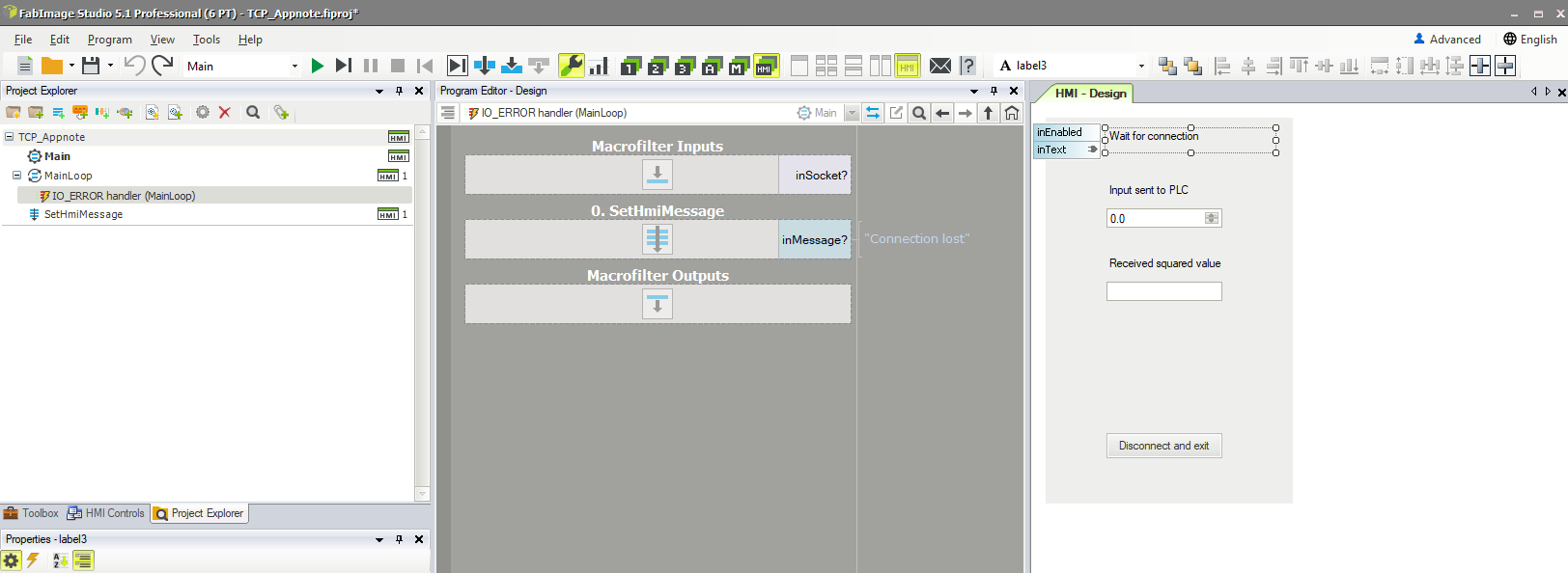
The result should look like in the following picture. If all previous steps have been done correctly, program should work without any problems.
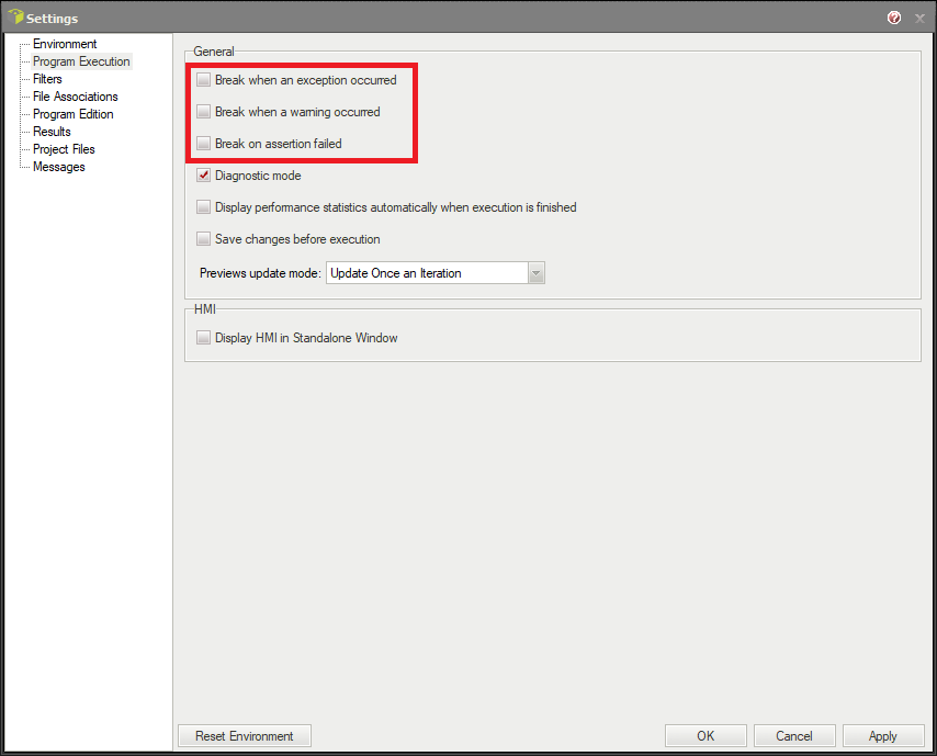
If you want to test program with occurring errors, you should unlock breaks in settings, as shown in the image below. With these settings, a pop-up window with error messages will not appear.