
You are here: Start » Application Notes » Interfacing Profinet gateway to FabImage Studio
Interfacing Profinet gateway to FabImage Studio
Purpose and equipment
This document explains how to configure Profinet PLC with FabImage Studio using Modbus-TCP - PROFINET gateway.
Required equipment:
- Supported Modbus-TCP - PROFINET gateway (used Anybus ABC4090);
- Siemens S7-1200 PLC;
- Ethernet switch with at least 5 In/Outs might be useful - simplifies configuration;
- TIA Portal (version v15 used);
- FabImage Studio 5.0 or later (version 5.2 used).
Application notes demonstrates configuration steps for specific gateway model, but it is not obligatory to use this one. If you have different gateway than the one described in Application Notes, please refer to manuals provided by its manufacturer.
Hardware connection
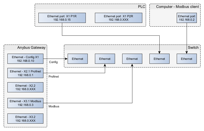
In application notes there is configured one network which uses Ethernet switch. Devices connected to this network have addresses 192.168.0.XXX, where XXX stands for number 1-254 unique for every device/port connected.
If you use Anybus ABC4090 gateway, it has 5 configurable In/Outs. Please find below description of these ports and connecting scheme:
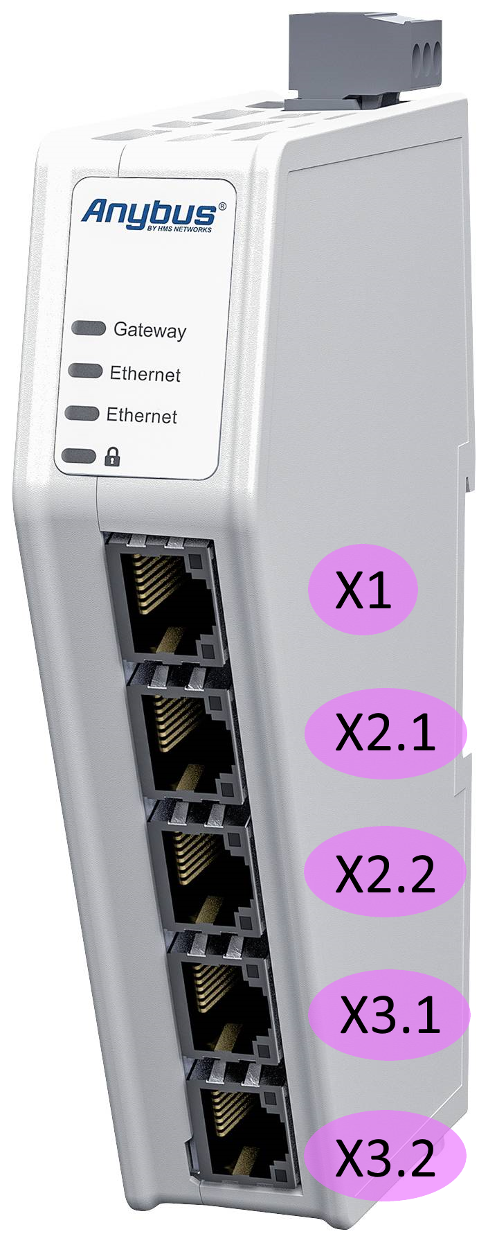
- X1 - Configuration port. By default this address is set to 192.168.0.10 and this address is used in this application notes. If you want to change it, use HMS IPconfig tool in the way described in ABC4090 configuration manual. Connected to switch.
- X2.1 - configurable port from network 1. Configured as Profinet. Connected to switch.
- X2.2 - configurable port from network 1. Configured as Profinet.
- X3.1 - configurable port from network 2. Configured as Modbus-TCP. Connected to switch.
- X3.2 - configurable port from network 2. Configured as Modbus-TCP.
Before proceeding to the further point, make sure that all devices are powered up.
Configuring Anybus gateway in web configurator
By default Anybus ABC4090 is configured as EtherNet/IP - PROFINET gateway. To have Modbus-TCP - PROFINET gateway there is need to upload new firmware to the device.
Please download appropriate drivers before further reading from firmware download section:
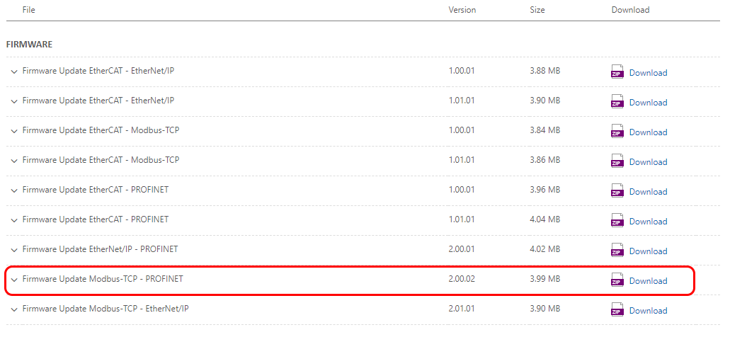
-
Default configuration IP address should be set to 192.168.0.10. PC must work in 192.168.0.0 network, so Ethernet-AnybusConfig IP were changed accordingly:
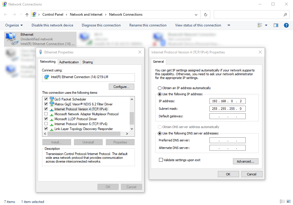
If you change network card's IP as shown above and you will connect it to the CONFIG port of the gateway you should be able to access configuration menu by typing 192.168.0.10 IP in the web browser:
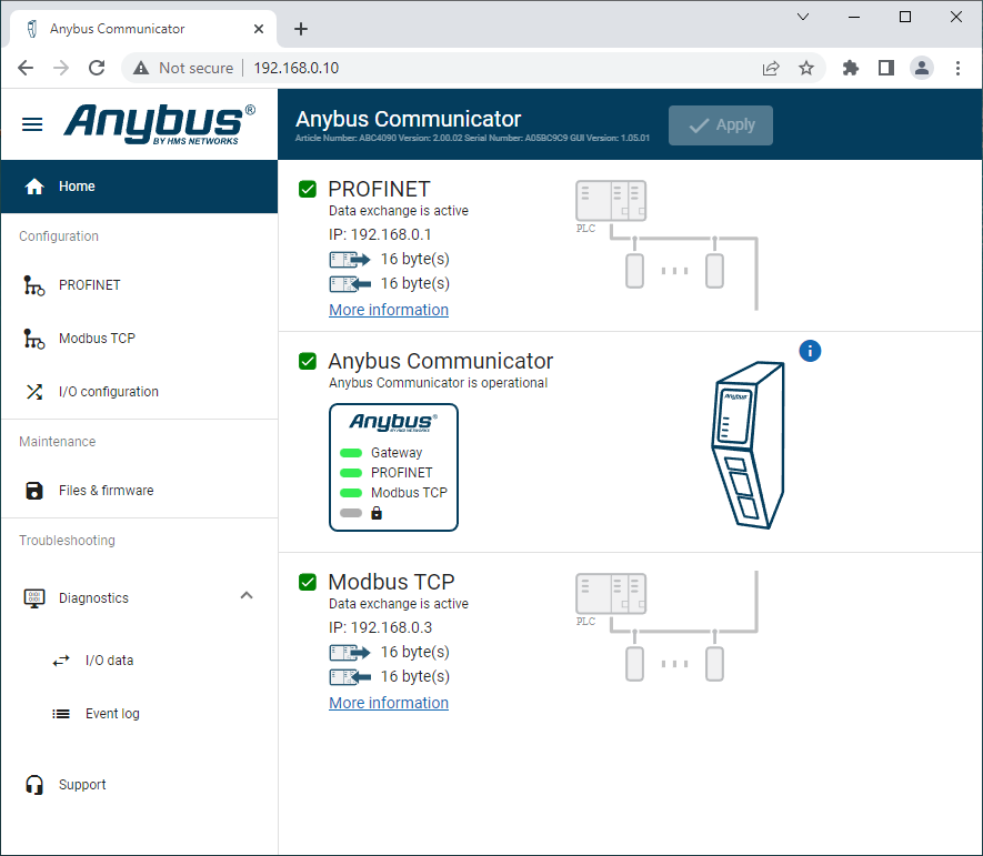
-
In order to change gateway's firmware navigate to Maintenance -> Files & firmware tab:
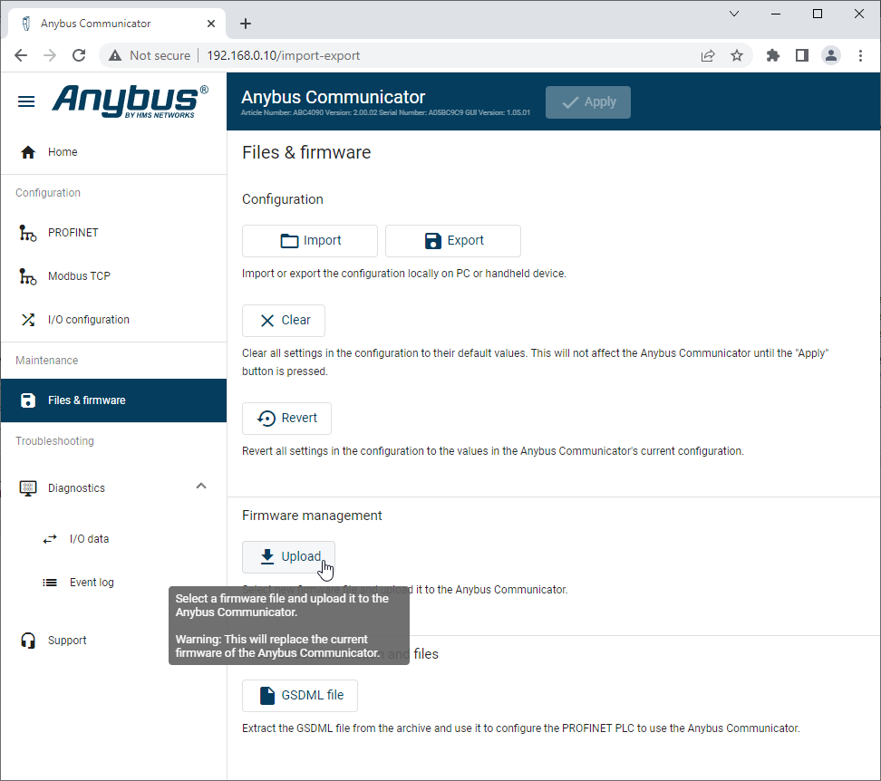
Click Upload and navigate to download firmware directory. It consists of GSDML file for later (hardware definition for Profinet PLC) and firmware file:
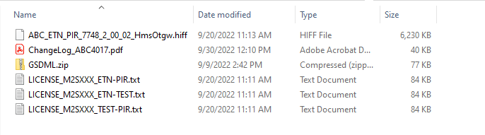
-
Devices linked should have an IP address which belongs to 192.168.0.0 network. Go to Configuration -> PROFINET tab, change settings like on the screen attached below and click Apply:
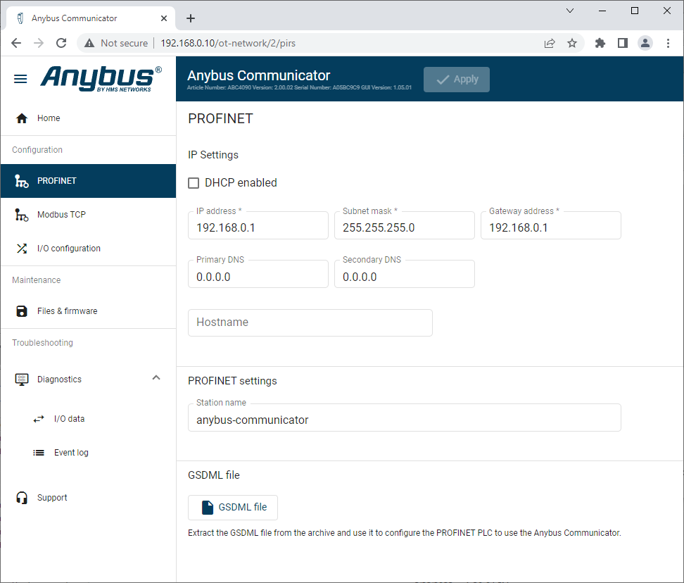
-
Devices linked should have an IP address which belongs to 192.168.0.0 network. Go to Configuration -> Modbus TCP tab, change settings like on the screen attached below and click Apply:
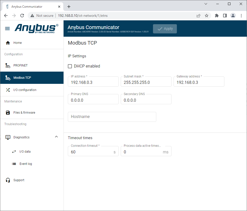
-
Navigate to I/O configuration tab, change settings like on the screen attached below and click Apply:
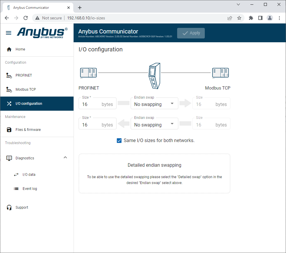
If your application requires more or less bytes to be exchanged feel free to change its values. It is important to have the same configuration in the gateway and in the PLC.
Configuring Anybus gateway in TIA Portal
This chapter describes how to configure PLC and gateway in TIA Portal software.
Reminding network connections, our PC with TIA Portal has to communicate with PLC controller in order to modify PLC program. Ethernet-Profinet connection is used and devices have an IP from 192.168.250.0 network:
List of IP addresses in network:
- PC - 192.168.0.2;
- PLC - 192.168.0.15;
- Gateway - 192.168.0.1
Please find attached below screens of hardware and software configuration from TIA Portal.
-
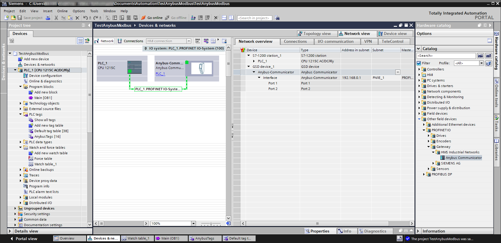
Create TIA Portal project with your PLC. Add GSD file from downloaded firmware folder in TIA Portal using tab menu on the top:
"Options → Manage general station … → Select file → Install".Once you upload GSD, you can find appropriate device in Other field devices -> PROFINET IO → Gateway → HMS Industrial Networks. Drag & drop it onto Network view and combine it as on the screen attached below:
-
Topology view is set up this way:
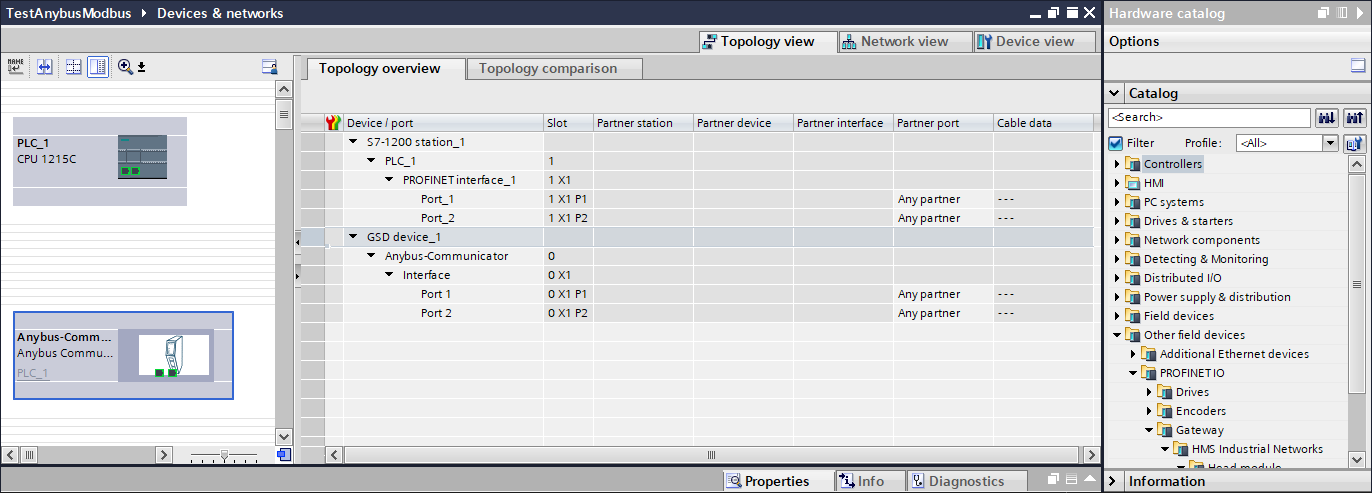
-
Change PLC's IP to 192.168.0.15:
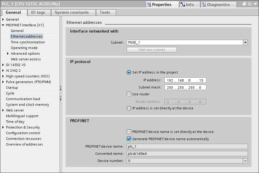
-
Change gateway's IP to 192.168.0.1:
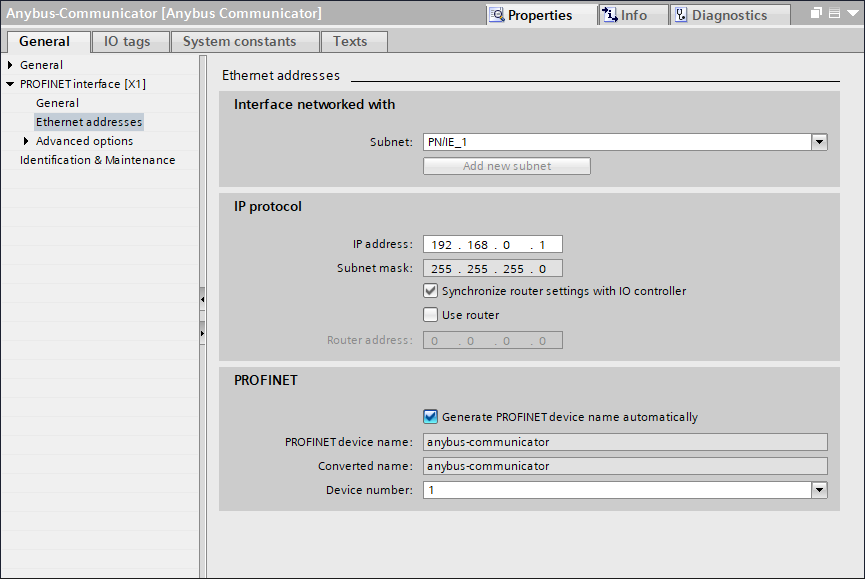
-
Add two modules to the project which match these configured in Anybus web configurator. Drag & drop IN 0016 and OUT 0016 module onto Device overview:
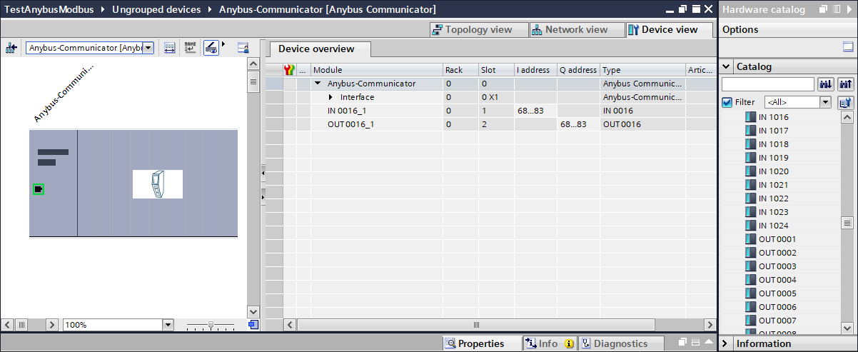
-
If all previous steps have been done correctly, your PLC program is ready. Compile the program and download it to the device. To see current states of variables, turn on Monitoring mode:


-
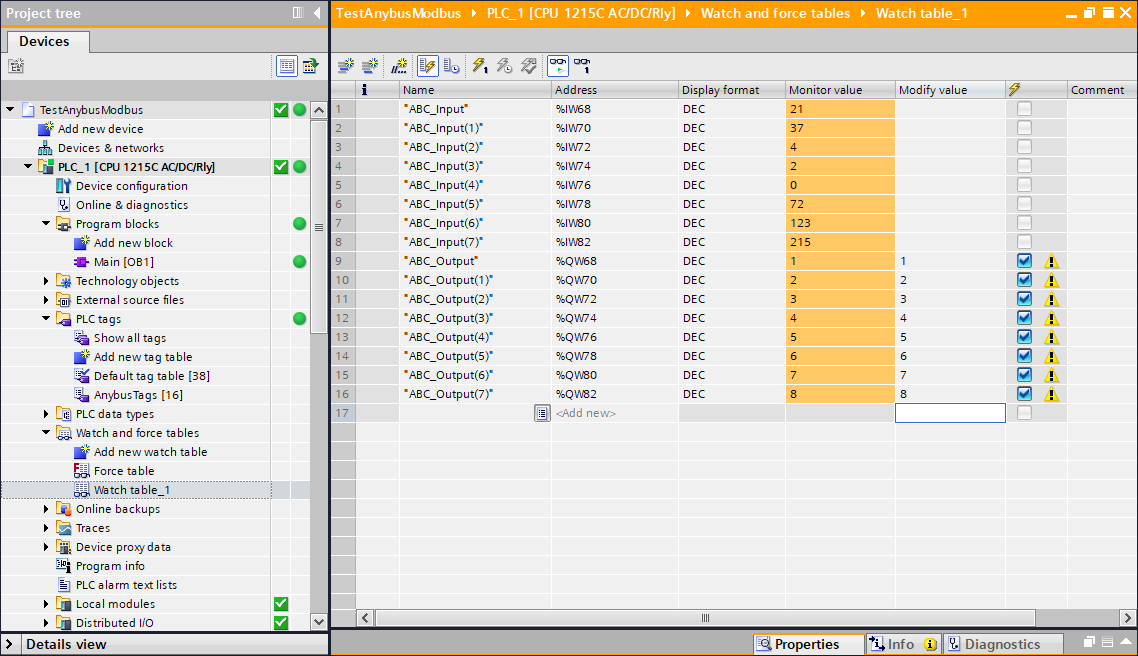
It is good manner to use gateways In/Outs by PLC tags - using raw addresses you can mistakenly modify/read wrong bytes. Create "AnybusTags" table in PLC tags folder:
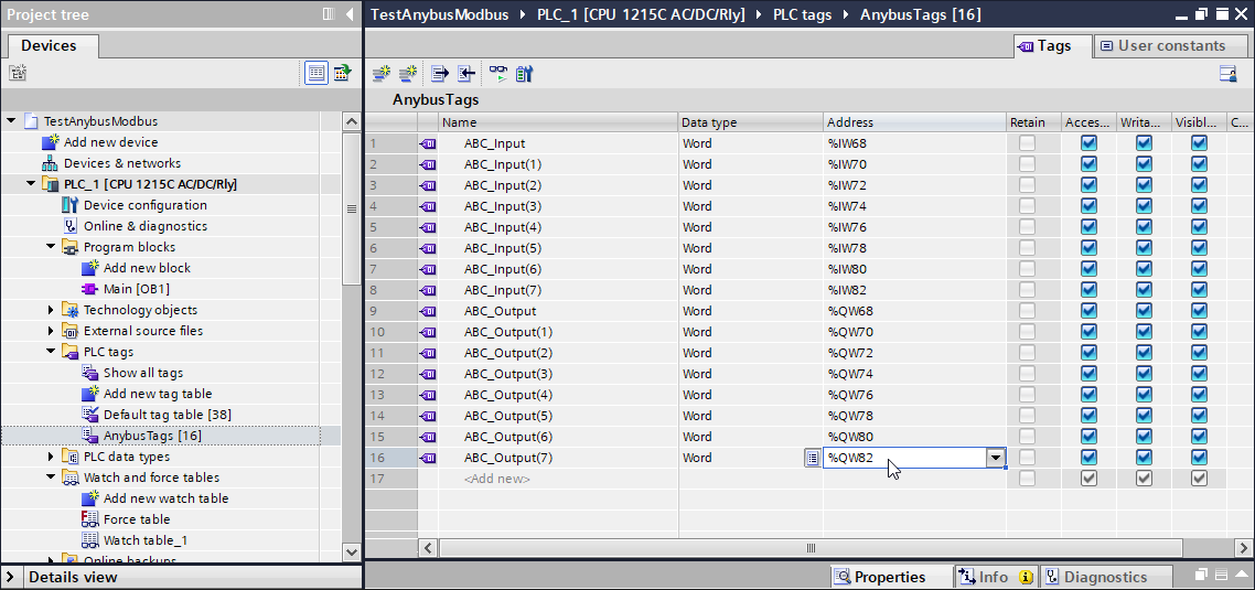
To monitor and easily modify tags please add Watch table in Watch and force tables folder.:
Configuring FabImage Studio application
-
FabImage Studio application should have ModbusTCP_Connect and I/O Read/Write filters as on the screen attached below:
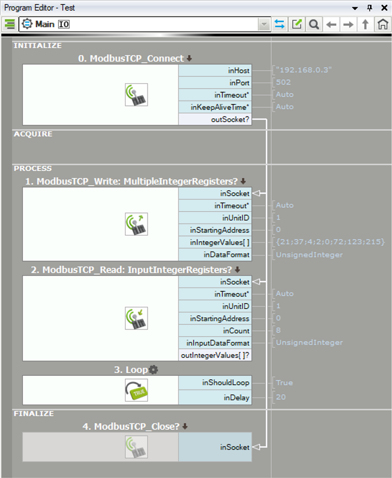
-
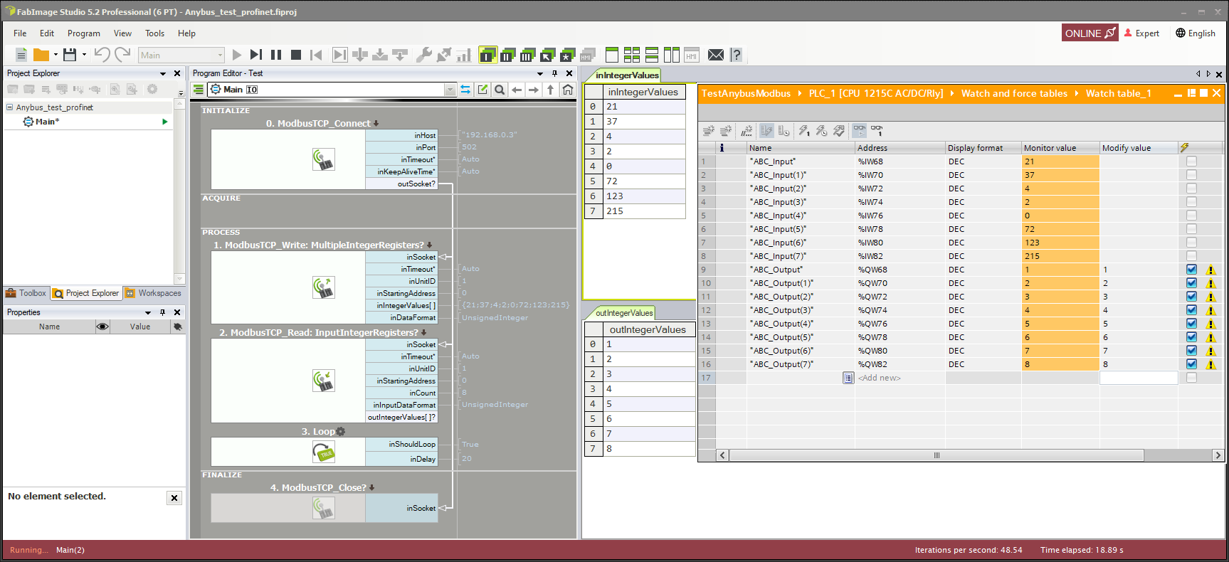
Turn on online mode and monitoring mode in TIA Portal. You can create watch tables to easily modify data in TIA Portal environment:
Troubleshooting
In case of any problem with gateway configuration, please try manuals and tutorial videos from Anybus support page.