You are here: Start » Blob Analysis
Blob Analysis
Introduction
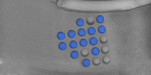
Blob Analysis is a fundamental technique of machine vision based on analysis of consistent image regions. As such it is a tool of choice for applications in which the objects being inspected are clearly discernible from the background. Diverse set of Blob Analysis methods allows to create tailored solutions for a wide range of visual inspection problems.
Main advantages of this technique include high flexibility and excellent performance. Its limitations are: clear background-foreground relation requirement (see Template Matching for an alternative) and pixel-precision (see 1D Edge Detection for an alternative).
Concept
Let us begin by defining the notions of region and blob.
- Region is any subset of image pixels. In FabImage Studio regions are represented using Region data type.
- Blob is a connected region. In FabImage Studio blobs (being a special case of region) are represented using the same Region data type. They can be obtained from any region using a single SplitRegionIntoBlobs filter or (less frequently) directly from an image using image segmentation filters from category Image Analysis techniques.
 |
 |
 |
An example image. |
Region of pixels darker than 128. |
Decomposition of the region into array of blobs. |
The basic scenario of the Blob Analysis solution consists of the following steps:
- Extraction - in the initial step one of the Image Thresholding techniques is applied to obtain a region corresponding to the objects (or single object) being inspected.
- Refinement - the extracted region is often flawed by noise of various kind (e.g. due to inconsistent lightning or poor image quality). In the Refinement step the region is enhanced using region transformation techniques.
- Analysis - in the final step the refined region is subject to measurements and the final results are computed. If the region represents multiple objects, it is split into individual blobs each of which is inspected separately.
Examples
The following examples illustrate the general schema of Blob Analysis algorithms. Each of the techniques represented in the examples (thresholding, morphology, calculation of region features, etc.) is inspected in detail in later sections.
Rubber Band
|
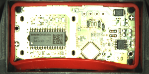
In this, idealized, example we analyze a picture of an electronic device wrapped in a rubber band. The aim here is to compute the area of the visible part of the band (e.g. to decide whether it was assembled correctly).
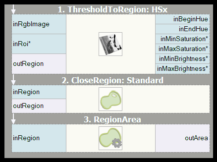
In this case each of the steps: Extraction, Refinement and Analysis is represented by a single filter. Extraction - to obtain a region corresponding to the red band a Color-based Thresholding technique is applied. The ThresholdToRegion_HSx filter is capable of finding the region of pixels of given color characteristics - in this case it is targeted to detect red pixels. Refinement - the problem of filling the gaps in the extracted region is a standard one. Classic solutions for it are the region morphology techniques. Here, the CloseRegion filter is used to fill the gaps. Analysis - finally, a single RegionArea filter is used to compute the area of the obtained region. |
Initial image 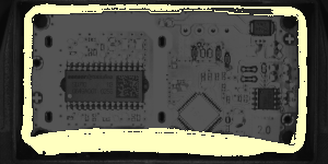
Extraction 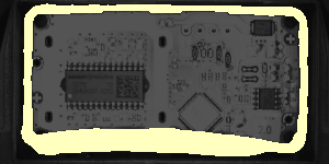
Refinement 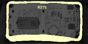
Results |
Mounts
|
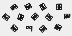
In this example a picture of a set of mounts is inspected to identify the damaged ones.
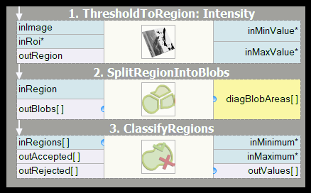
Extraction - as the lightning in the image is uniform, the objects are consistently dark and the background is consistently bright, the extraction of the region corresponding to the objects is a simple task. A basic ThresholdToRegion filter does the job, and does it so well that no Refinement phase is needed in this example. Analysis - as we need to analyze each of the blobs separately, we start by applying the SplitRegionIntoBlobs filter to the extracted region. To distinguish the bad parts from the correct parts we need to pick a property of a region (e.g. area, circularity, etc.) that we expect to be high for the good parts and low for the bad parts (or conversely). Here, the area would do, but we will pick a somewhat more sophisticated rectangularity feature, which will compute the similarity-to-rectangle factor for each of the blobs. Once we have chosen the rectangularity feature of the blobs, all that needs to be done is to feed the regions to be classified to the ClassifyRegions filter (and to set its inMinimum value parameter). The blobs of too low rectangularity are available at the outRejected output of the classifying filter. |

Input image 
Extraction 
Analysis 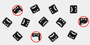
Results |
Extraction
There are two techniques that allow to extract regions from an image:
- Image Thresholding - commonly used methods that compute a region as a set of pixels that meet certain condition dependent on the specific operator (e.g. region of pixels brighter than given value, or brighter than the average brightness in their neighborhood). Note that the resulting data is always a single region, possibly representing numerous objects.
- Image Segmentation - more specialized set of methods that compute a set of blobs corresponding to areas in the image that meet certain condition. The resulting data is always an array of connected regions (blobs).
Thresholding
Image Thresholding techniques are preferred for common applications (even those in which a set of objects is inspected rather than a single object) because of their simplicity and excellent performance. In FabImage Studio there are six filters for image-to-region thresholding, each of them implementing a different thresholding method.
| Brightness-based (basic) |
 |
 |
|---|---|---|
| Brightness-based (additional) |
 |
|
| Color-based |  |
 |
Classic Thresholding
ThresholdToRegion simply selects the image pixels of the specified brightness. It should be considered a basic tool and applied whenever the intensity of the inspected object is constant, consistent and clearly different from the intensity of the background.
 |
 |
Dynamic Thresholding
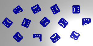
Inconsistent brightness of the objects being inspected is a common problem usually caused by the imperfections of the lightning setup. As we can see in the example below, it is often the case that the objects in one part of the image actually have the same brightness as the background in another part of the image. In such case it is not possible to use the basic ThresholdToRegion filter and ThresholdToRegion_Dynamic should be considered instead. The latter selects image pixels that are locally bright/dark. Specifically - the filter selects the image pixels of the given relative local brightness defined as the difference between the pixel intensity and the average intensity in its neighborhood.
 |
 |
Color-based Thresholding
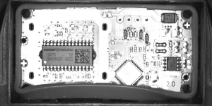
When inspection is conducted on color images it may be the case that despite a significant difference in color, the brightness of the objects is actually the same as the brightness of their neighborhood. In such case it is advisable to use Color-based Thresholding filters: ThresholdToRegion_RGB, ThresholdToRegion_HSx. The suffix denote the color space in which we define the desired pixel characteristic and not the space used in the image representation. In other words - both of these filters can be used to process standard RGB color image.
 |
 |
 |
An example image. |
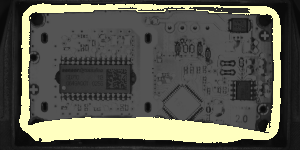
Mono equivalent of the image depicting brightness of its pixels. |
Result of the color-based thresholding targeted at red pixels. |
Refinement
Region Morphology
Region Morphology is a classic technique of region transformation. The core concept of this toolset is the usage of a structuring element also known as the kernel. The kernel is a relatively small shape that is repeatedly centered at each pixel within dimensions of the region that is being transformed. Every such pixel is either added to the resulting region or not, depending on operation-specific condition on the minimum number of kernel pixels that have to overlap with actual input region pixels (in the given position of the kernel). See description of Dilation for an example.
| Expanding | Reducing | |
|---|---|---|
| Basic |  |
 |
| Composite |  |
 |
Dilation and Erosion
Dilation is one of two basic morphological transformations. Here each pixel P within the dimensions of the region being transformed is added to the resulting region if and only if the structuring element centered at P overlaps with at least one pixel that belongs to the input region. Note that for a circular kernel such transformation is equivalent to a uniform expansion of the region in every direction.
 |
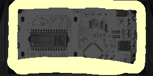 |
Erosion is a dual operation of Dilation. Here, each pixel P within the dimensions of the region being transformed is added to the resulting region if and only if the structuring element centered at P is fully contained in the region pixels. Note that for a circular kernel such transformation is equivalent to a uniform reduction of the region in every direction.
 |
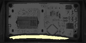 |
Closing and Opening
The actual power of the Region Morphology lies in its composite operators - Closing and Opening. As we may have recently noticed, during the blind region expansion performed by the Dilation operator, the gaps in the transformed region are filled in. Unfortunately, the expanded region no longer corresponds to the objects being inspected. However, we can apply the Erosion operator to bring the expanded region back to its original boundaries. The key point is that the gaps that were completely filled during the dilation will stay filled after the erosion. The operation of applying Erosion to the result of Dilation of the region is called Closing, and is a tool of choice for the task of filling the gaps in the extracted region.
 |
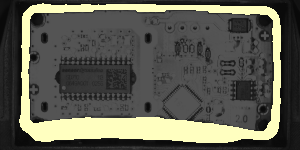 |
Opening is a dual operation of Closing. Here, the region being transformed is initially eroded and then dilated. The resulting region preserves the form of the initial region, with the exception of thin/small parts, that are removed during the process. Therefore, Opening is a tool for removing the thin/outlying parts from a region. We may note that in the example below, the Opening does the - otherwise relatively complicated - job of finding the segment of the rubber band of excessive width.
 |
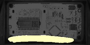 |
Other Refinement Methods
Analysis
Once we obtain the region that corresponds to the object or the objects being inspected, we may commence the analysis - that is, extract the information we are interested in.
Region Features
FabImage Studio allows to compute a wide range of numeric (e.g. area) and non-numeric (e.g. bounding circle) region features. Calculation of the measures describing the obtained region is often the very aim of applying the blob analysis in the first place. If we are to check whether the rectangular packaging box is deformed or not, we may be interested in calculating the rectangularity factor of the packaging region. If we are to check if the chocolate coating on a biscuit is broad enough, we may want to know the area of the coating region.
It is important to remember, that when the obtained region corresponds to multiple image objects (and we want to inspect each of them separately), we should apply the SplitRegionIntoBlobs filter before performing the calculation of features.
Numeric Features
Each of the following filters computes a number that expresses a specific property of the region shape.
Annotations in brackets indicate the range of the resulting values.
Non-numeric Features
Each of the following filters computes an object related to the shape of the region. Note that the primitives extracted using these filters can be made subject of further analysis. For instance, we can extract the holes of the region using the RegionHoles filter and then measure their areas using the RegionArea filter.
Annotations in brackets indicate FabImage Studio's type of the result.
Case Studies
Capsules

In this example we inspect a set of washing machine capsules on a conveyor line. Our aim is to identify the deformed capsules.
We will proceed in two steps: we will commence by designing a simple program that, given picture of the conveyor line, will be able to identify the region corresponding to the capsule(s) in the picture. In the second step we will use this program as a building block of the complete solution.
FindRegion Routine
|
In this section we will develop a program that will be responsible for the Extraction and Refinement phases of the final solution. For brevity of presentation in this part we will limit the input image to its initial segment.
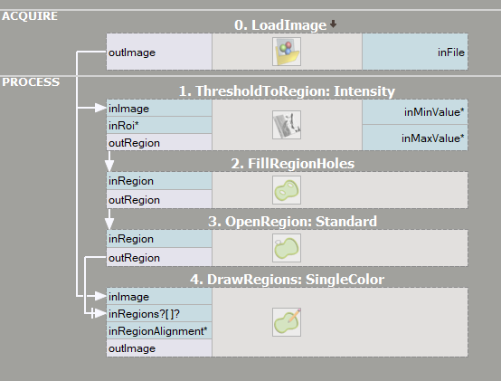
After a brief inspection of the input image we may note that the task at hand will not be trivial - the average brightness of the capsule body is similar to the intensity of the background. On the other hand the border of the capsule is consistently darker than the background. As it is the border of the object that bears significant information about its shape we may use the basic ThresholdToRegion filter to extract the darkest pixels of the image with the intention of filling the extracted capsule border during further refinement. The extracted region certainly requires such refinement - actually, there are two issues that need to be addressed. We need to fill the shape of the capsule and eliminate the thin horizontal stripes corresponding to the elements of the conveyor line setup. Fortunately, there are fairly straightforward solutions for both of these problems. FillRegionHoles will extend the region to include all pixels enclosed by present region pixels. After the region is filled all that remains is the removal of the thin conveyor lines using the classic OpenRegion filter. |
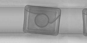
Initial image 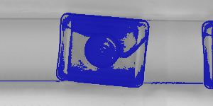
ThresholdToRegion 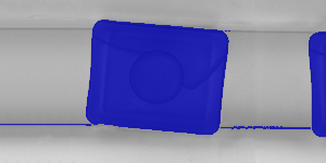
FillRegionHoles 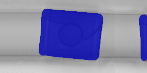
OpenRegion |
Our routine for Extraction and Refinement of the region is ready. As it constitutes a continuous block of filters performing a well defined task, it is advisable to encapsulate the routine inside a function to enhance the readability of the soon-to-be-growing program.
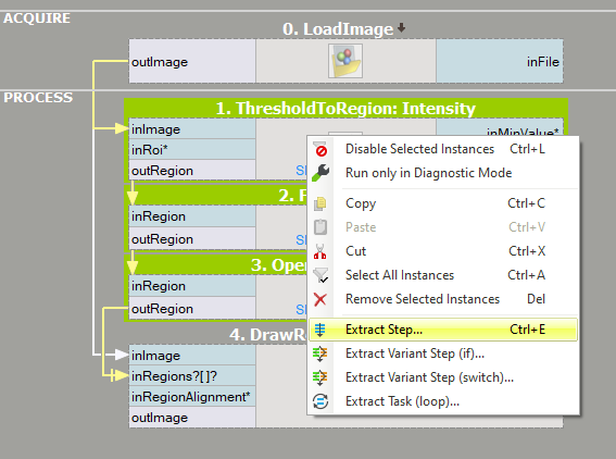 |
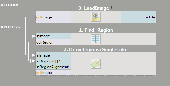 |
Complete Solution
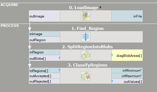
Our program right now is capable of extracting the region that directly corresponds to the capsules visible in the image. What remains is to inspect each capsule and classify it as a correct or deformed one.
As we want to analyze each capsule separately, we should start with decomposition of the extracted region into an array of connected components (blobs). This common operation can be performed using the straightforward SplitRegionIntoBlobs filter.
We are approaching the crucial part of our solution - how are we going to distinguish correct capsules from deformed ones? At this stage it is advisable to have a look at the summary of numeric region features provided in Analysis section. If we could find a numeric region property that is correlated with the nature of the problem at hand (e.g. it takes low values for a correct capsules and high values for a deformed one, or conversely), we would be nearly done.
Rectangularity of a shape is defined as the ratio between its area and area of its smallest enclosing rectangle - the higher the value, the more the shape of the object resembles a rectangle. As the shape of a correct capsule is almost rectangular (it is a rectangle with rounded corners) and clearly more rectangular than the shape of deformed capsule, we may consider using rectangularity feature to classify the capsules.
Having selected the numeric feature that will be used for the classification, we are ready to add the ClassifyRegions filter to our program and feed it with data. We pass the array of capsule blobs on its inRegions input and we select Rectangularity on the inFeature input. After brief interactive experimentation with the inMinimum threshold we may observe that setting the minimum rectangularity to 0.95 allows proper discrimination of correct (available at outAccepted) and deformed (outRejected) capsule blobs.

Region extracted by the FindRegion routine.

Decomposition of the region into individual blobs.

Blobs of low rectangularity selected by ClassifyRegions filter.
| Previous: Image Processing | Next: 1D Edge Detection |


 )
)


