
You are here: Start » Program Examples » Heater Control
Heater Control
Aim:
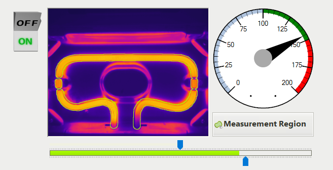
The task is to emulate heater control with HMI and interpret data from a thermal camera monitoring the heater. Data should be presented as a heatmap. The Temperature of the heater should be measured in Celsius degrees.
Input:
Raw data from a thermal camera, and inputs from the HMI.
Output:
Data from the thermal camera showed as a Heatmap, and the measurement of the temperature of the heater in Celsius degrees.
Hints:
Data from the thermal camera contains a temperature value for each pixel, with can be displayed as a picture, but a formula provided from the camera manufacturer must be used to transform this data into Celsius degrees. This formula is:
C = X*0.04 - 273.15
The result image can be converted to HeatMap with the ColorizeImage filter.
To measure the temperature of the heater, a custom region needs to be prepared that matches the heater area, and not the background.
Solution (FIS):
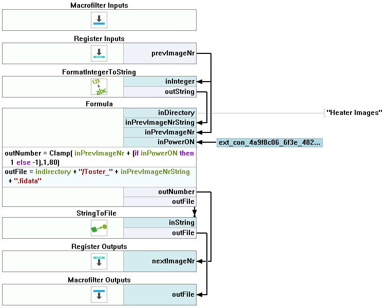
The example program has an added emulation of a switch, to turn the heater on and off, and an additional task for fluid control of the color change of HMI indicators. These elements are optional, and as such, are not needed for the program to work properly. The optional parts are in ChoseImage and AdjustTrackBarColorToTemp Tasks.
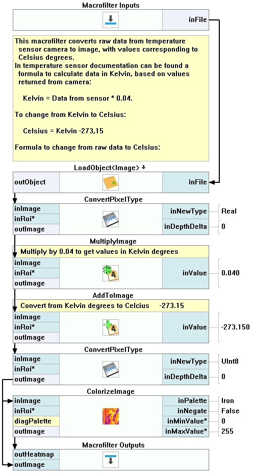
Generate an image with pixel values corresponding to Celsius degree, and colorize it, to look like an image from a thermal camera. Lest check the GenerateHeatmap task.
-
Navigate to Examples\Heater Control (Thermal Imaging) in your FabImage Studio install directory. The Heater Images folder contains .fidata files.
-
Drag and drop the Heater Images folder into the Acquire section of the program. It should insert the EnumerateObjects filter. Data from thermal camera are interpreted as an image with the UInt16 data type.
-
To be able to perform operations on this image, convert the pixel type to Real, using the ConvertPixelType filter.
-
Next, the data from the thermal camera needs to be changed to Celsius degrees. To do this, use the MultiplyImage and AddToImage filters, to process the image according to the formula:
C = X*0.04 - 273.15
-
The result image has values corresponding to Celsius degrees. If you use a color picker tool to inspect image, is should return a value in Celsius degrees, but it is in Real pixel format. Most tools use UInt8 format, so use the ConvertPixelType once again.
-
To get a Heatmap, use the ColorizeImage filter. You can choose from several available color palettes. As the goal of this example is to recreate thermal camera vision, the Iron palette is best suited.
-
Place view2DBox1 on the HMI, and connect theoutImage of ColorizeImage to the inImage input.
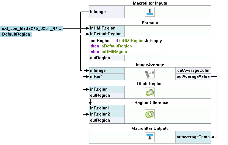
Measure average temperature of heater. This is done inside CalculateHeaterTemperature
-
Use ImageAverage filter, to get average pixel value of heater. You can set region manually, or use regionEditor1 on HMI to have possibility of setting Roi from HMI. In this case it is advised to prepare an default region in case region from HMI is cleared.
-
To generate the outline of the selected region, use DilateRegion and RegionDifference filters, and connect them to the inData1 input of view2DBox1.
Macrofilter Main
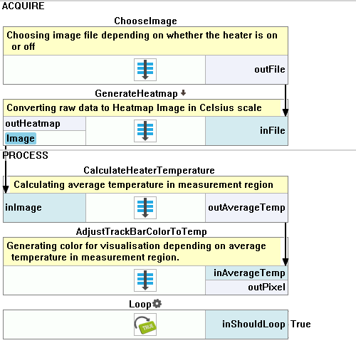
Macrofilter ChooseImage
Macrofilter GenerateHeatmap
Macrofilter CalculateHeaterTemperature
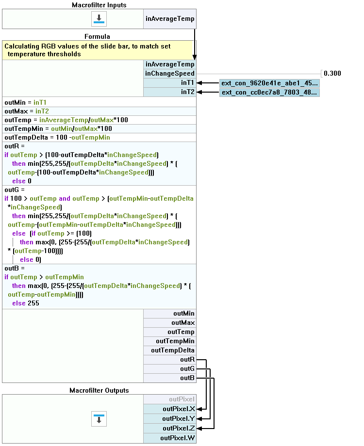
Macrofilter AdjustTrackBarColorToTemp
Further Readings
- Formulas - Detailed information about using formulas.
- HMI Controls - List of HMI controls.
- Image Analysis - List of filters analyzing images.
- Image Processing - A comprehensive introduction to Image Processing.