You are here: Start » Program Examples » Calibration with Editor on Remapped Images
Calibration with Editor on Remapped Images
Aim:
The goal is to compute the world coordinates of the dots based on provided images of the calibration grid.
Input:
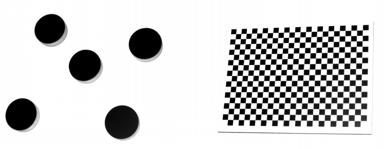
A few images of the calibration grid and the dots.
Output:
The coordinates of the found dots.
Hints:
First of all, as there are both lens and perspective distortion, they need to be removed by using the RectifyImage filter. Next, to correctly locate the dots, it is best to use the ExtractBlobs_Intensity. Eventually, to find the center points of circles, try fitting a corresponding shape to them and use an appropriate property output.
Solution (FIS):
-
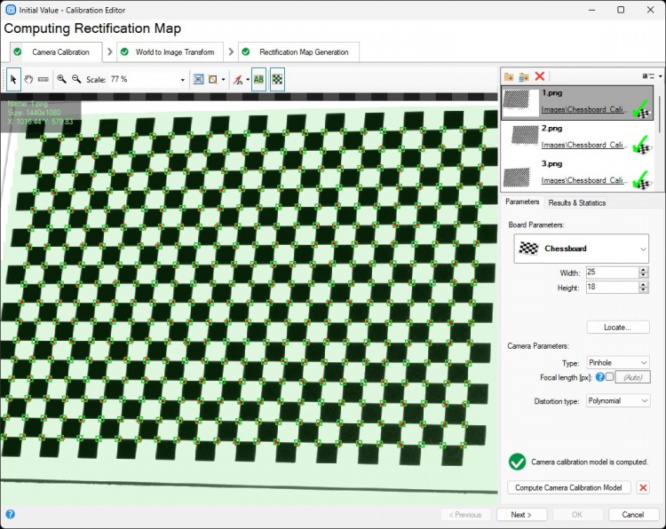
In the Project Explorer section, create a Global Parameter named RectificationMap of RectificationMap type. In the Initial Value section, click on the three dots button to open the editor.
-
In the first step of calibration, remove lens distortion:
- Load an image with the calibration grid.
- Choose the Chessboard type.
- Count the chessboard squares horizontally and vertically and enter the numbers in the parameters section.
- Use the Locate button to find calibration points.
- Calibration will be most precise within the green area. In order to achieve best performance on the entire picture, the calibration grid should cover it completely. You can use a number of pictures to achieve this. Just load them into the editor on the right.
- Use Compute Calibration Model to calculate the Camera calibration model and activate the next step.
-
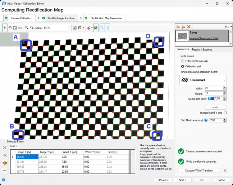
In the second step of the calibration, we will determine the transformation between Real-world points and image points:
- Load an image with the calibration grid.
- Choose Calibration grid.
- Choose the Chessboard type and fill in the Width and the Height information as in the previous step. Set the Square size as 7,5.
- Use the Locate button to find calibration points.
- Select the black cursor icon.
- Click on point A. In the table with points, insert World X [mm]: 0 and World Y [mm]: 0.
- Click on point B. In the table with points,insert World X [mm]: 0 and World Y [mm]: 120.
- Click on point C. In the table with points, insert World X [mm]: 172,5 and World Y [mm]: 120.
- Click on point D. In the table with points, insert World X [mm]: 172,5 and World Y [mm]: 0.
- Click the Compute World Transform button.
- Click the Next > button.
-
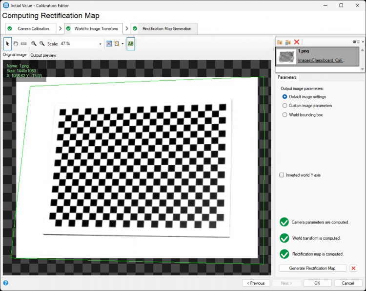
The last step of the calibration is used to set parameters of the image after rectification:
- Load an image with the calibration grid.
- Click the Generate Rectification Map button.
- Click the OK button.
-
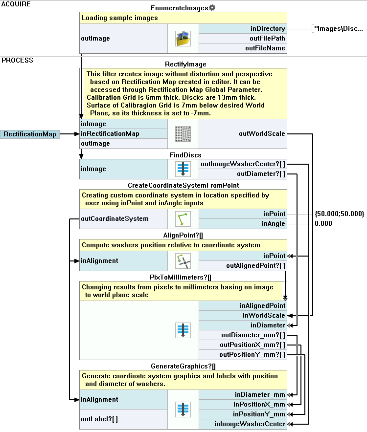
In the ACQUIRE section of the application, add the EnumerateImages filter and set the inDirectory to the location of the dots' images.
-
In the PROCESS section, add the RectifyImage filter. Connect the inRectificationMap input to the RectificationMap parameter and the inImage input to the EnumerateImages outImage output.
-
Create a new Step macrofilter named FindDiscs. Drag the RectifyImage outImage output to the new macrofilter to create the input.
-
Go to the FindDiscs macrofilter. Add the ExtractBlobs_Intensity filter. Connect its inImage input to the macrofilter's input.
-
Add 2 ClassifyRegions filters:
- For the first one, connect the inRegions input to the ExtractBlobs_Intensity outBlobs output and set the inMinimum to 30000.
- For the second one, connect the inRegions input to the outAccepted output of the previous filter. Set the inFeature to Circularity_BoundingCirclePreserving and the inMinimum to 0.9.
-
Add the RegionBoundingCircle_OrNil filter and connect its input to the last ClassifyRegions outAccepted output.
-
Add the FitCircleToEdges filter:
- Connect the inImage input to the macrofilter's input.
- For the inFittingField, connect the Axis to the RegionBoundingCircle_OrNil output and set the Width to 40.
- Expand the outputs to get the outAlignedFittingField Axis.Radius value.
- Drag the outAlignedFittingField Axis output to the Macrofilter Outputs section and name the new output ImageWasherCenter.
- Drag the outCircle output to the Macrofilter Outputs section and name the new output WorldCircles.
-
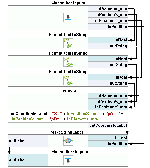
Add a formula. Drag the outAlignedFittingField Axis.Radius output from the previous filter to create the input and name it Radius.
outDiameter = inRadius * 2
-
Drag the formula output to the Macrofilter Outputs section.
-
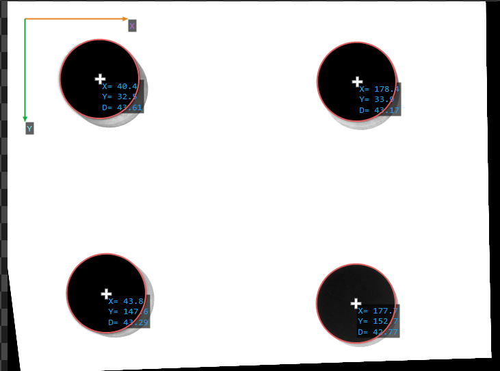
Go back to the Main macrofilter. Add the CreateCoordinateSystemFromPoint filter. Set the inPoint input as {50;50}.
-
Add the AlignPoint filter. Connect its inAlignment input to the CreateCoordinateSystemFromPoint output and the inPoint input to the ImageWasherCenter output of the FindDiscs macrofilter.
-
Create a new Step macrofilter named PixToMillimeters. Drag to it:
- the AlignPoint output
- the RectifyImage outWorldScale output
- the Diameter output of the FindDiscs macrofilter.
-
Inside the PixToMillimeters macrofilter:
- Label the WorldScale input.
- Expand the AlignedPoint input to get X and Y values separately.
- Add 3 PixelsToMillimetres filters:
- Connect the inScale input with the WorldScale for each new filter.
- For the first one, connect the inPixels to the Diameter macrofilter's input.
- For the second one, connect the inPixels to the X macrofilter's input.
- For the third one, connect the inPixels to the Y macrofilter's input.
- Connect each PixelsToMillimetres outputs to the macrofilter's output and name them: Diameter_mm, PositionX_mm and PositionY_mm.
-
Go back to the Main macrofilter. Create a new Step macrofilter named GenerateGraphics. Drag to it:
- all the PixToMillimeters macrofilter outputs
- the CreateCoordinateSystemFromPoint filter output
- the ImageWasherCenter output of the FindDiscs macrofilter.
-
Inside the GenerateGraphics create 2 Step macrofilters and name them VisualizeCoordinateSystem and CreateLabels. Drag the Alignment macrofilter input to the VisualizeCoordinateSystem step and all the rest of the inputs to the CreateLabels.
-
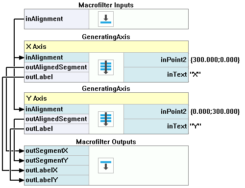
Inside the VisualizeCoordinateSystem macrofilter create a new Step macrofilter. Name it GeneratingAxis. Create 3 inputs of it:
- the Alignment of the CoordinateSystem2D type
- the Point2 of the Point2D type
- the Axis of the String type
-
Inside the GeneratingAxis macrofilter:
- Add the MakeSegment filter. Connect the inPoint2 input to the macrofilter's Point2 input.
- Add the AlignSegment filter. Connect the inSegment input to the previous filter's output. Connect the inAlignment input to the macrofilter's Alignment input. Expand the outputs to get the outAlignedSegment Point2 value. Drag the outAlignedSegment output to the Macrofilter Outputs section.
- Add the MakeStringLabel filter. Connect the inText input to the macrofilter's Axis input. Connect the inPosition input to the Point2 output of the previous filter. Drag the outLabel output to the Macrofilter Outputs section to create a new output.
Macrofilter Main.
Macrofilter CreateLabels.
Macrofilter FindDiscs.
Macrofilter GenerateGraphics.
Macrofilter GeneratingAxis.
Macrofilter PixToMillimeters.
Macrofilter VisualizeCoordinateSystem.