
You are here: Start » Filter Reference » Computer Vision » Shape Fitting » FitPathToEdges
 Basic
Basic| Module: | MetrologyPro |
|---|
Performs a series of 1D edge detections and creates a path from the detected points.
Applications
| Name | Type | Range | Description | |
|---|---|---|---|---|
 |
inImage | Image | Image to fit the path to | |
|
inFittingField | PathFittingField | Path fitting field | |
|
inFittingFieldAlignment | CoordinateSystem2D* | Adjusts the fitting field to the position of the inspected object | |
|
inScanStep | Real* | 0.0 -  |
Optional implicit conversion of the input path to an equidistant one |
|
inScanWidth | Integer | 1 - |
The width of each scan field (in pixels) |
|
inSamplingParams | SamplingParams | Parameters controlling the sampling process | |
|
inEdgeScanParams | EdgeScanParams | Parameters controlling the edge extraction process | |
|
inEdgeSelection | Selection | Selection mode of edges | |
|
inLocalBlindness | LocalBlindness* | Defines conditions in which weaker edges can be detected in the vicinity of stronger edges | |
|
inMaxInterpolationLength | Integer* | 0 - |
Maximal number of consecutive points not found |
|
inMaxDeviationDelta | Real* | 0.0 - |
Maximal difference between deviations of consecutive path points |
|
inMaxIncompleteness | Real | 0.0 - 0.999 | Maximal fraction of edge points not found |
 |
outPath | Path? | Fitted path or nothing if the fitting failed | |
|
outEdges | Edge1D?Array | Found edges | |
|
outDeviationProfile | Profile? | Profile of distances between the actual path points and the corresponding reference path points | |
|
outAlignedFittingField | PathFittingField | Fitting field used; in the image coordinate system | |
|
outBrightnessProfiles | ProfileArray | Extracted image profiles | |
|
outResponseProfiles | ProfileArray | Profiles of the edge (derivative) operator response | |
 |
diagScanSegments | Segment2DArray | Segments along which the scans were run | |
|
diagSamplingAreas | Rectangle2DArray | Areas from which the input image is sampled | |
Description
The operation tries to fit a given path to edges present in the inImage image. Internally, it performs a series of scans with the ScanSingleEdge filter along a number of specific scan segments which length is always equal to the inFittingField width and cannot be less than 4. The found points are then used to determine the actual position of the path in the image. Only inMaxIncompleteness fraction of these scans may fail. If the fitting according to the given parameters is not possible, outPath is set to Nil.
There are also another parameters that control the path fitting process. The inMaxDeviationDelta parameter defines the maximal allowed difference between deviations of consecutive points from the input path points. If some of the scans fail or if some of found points are classified to be wrong according to another control parameters, output path points corresponding to them are interpolated depending on points in their nearest vicinity. No more than inMaxInterpolationLength consecutive points can be interpolated. The exception to this behavior are points which were not found on both ends of the input path. Those are not part of the result at all.
Hints
- Connect an input image to the inImage input.
- If the object location is variable, connect inFittingFieldAlignment to an appropriate local coordinate system (e.g. from a template matching filter).
- Define the inFittingField input to specify the area in which edge scanning will be performed.
- Define inEdgeScanParams.EdgeTransition to detect a particular edge type, and only that type.
- If the noise level is high, try increasing inScanWidth and/or inEdgeScanParams.SmoothingStdDev.
- If no or too few edge points are found, try decreasing inEdgeScanParams.MinMagnitude.
- If some of the scans may fail, set the inMaxIncompleteness input accordingly.
- Use the diagScanSegments and outEdges outputs to visualize the scanning results.
Examples
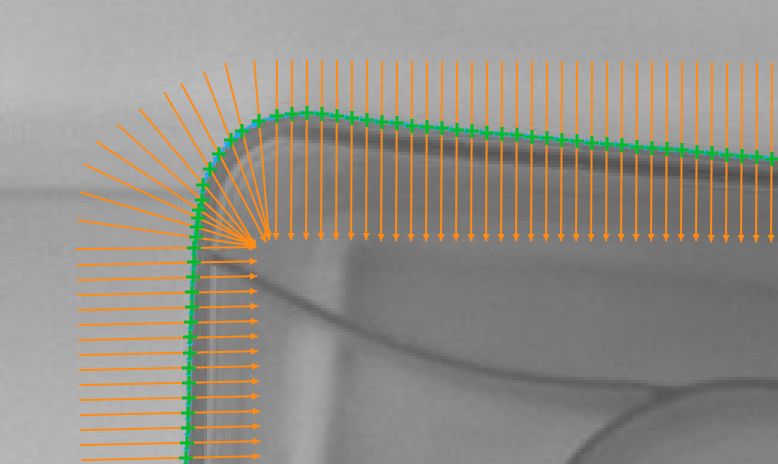
Fitting a path to the edges of a plastic capsule
(inEdgeSelection = First, inEdgeScanParams.EdgeTransition = BrightToDark).
Remarks
Read more about Local Coordinate Systems in Machine Vision Guide: Local Coordinate Systems.
This filter is a part of the Shape Fitting toolset. To read more about this technique, one can refer to the Shape Fitting chapter of our Machine Vision Guide
Hardware Acceleration
This operation supports automatic parallelization for multicore and multiprocessor systems.
Complexity Level
This filter is available on Basic Complexity Level.
Filter Group
This filter is member of FitPath filter group.
See Also
- FitPathToRidges – Performs a series of 1D ridge detections and creates a path from the detected points.
- FitPathToStripe – Performs a series of 1D stripe detections and creates a path from the detected points.