
You are here: Start » Program Examples » Calibration World Coordinates With Remapped Images
Calibration World Coordinates With Remapped Images
Aim
The goal is to compute the world coordinates based on given images of the calibration grid.
Input
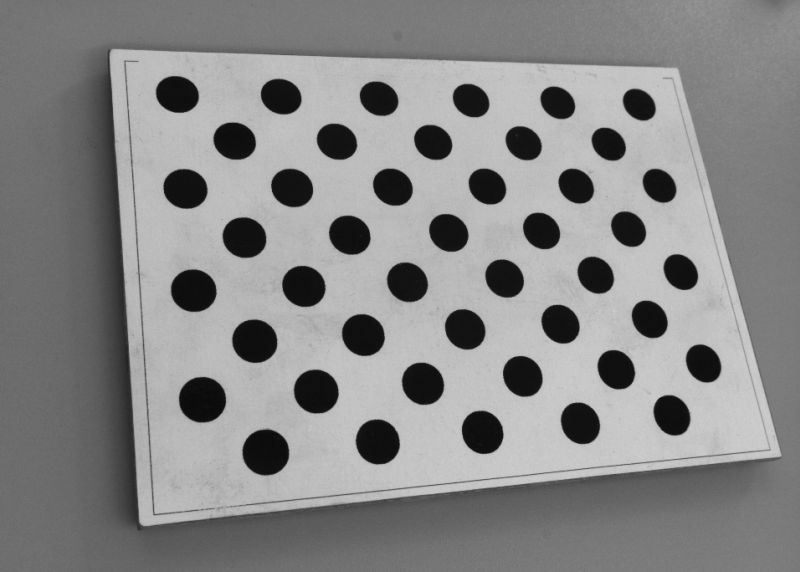
A few images of the calibration grid.
Output
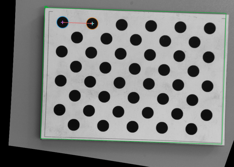
Located calibration grid and center points of two first circles on the board.
Hints
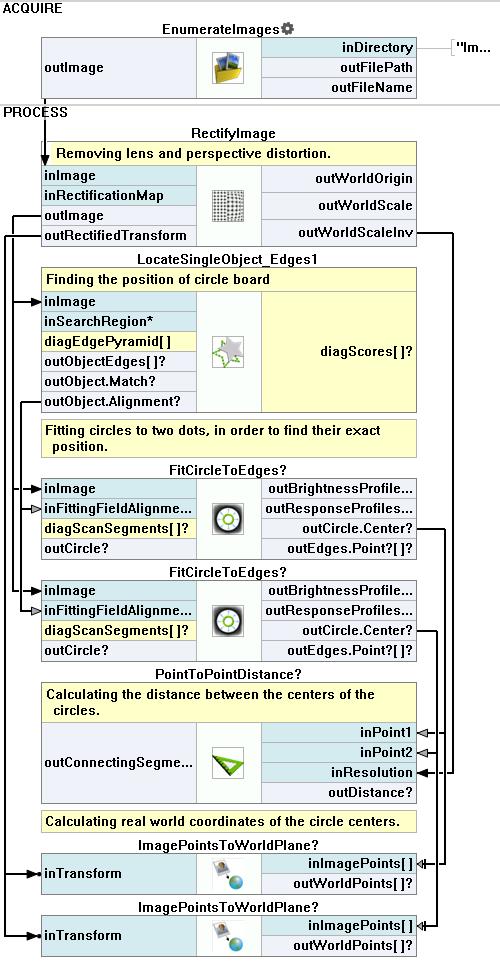
First of all, as there are both lens and perspective distortion, they need to be removed by using the RectifyImage filter. Next, to correctly locate the circle board it is best to use the LocateSingleObject_Edges1. Eventually, to find the center points of circles, try fitting a corresponding shape to them and use an appropriate property output.
Solution (FIS)
-
Add the EnumerateImages and specify the directory to images in the inDirectory.
-
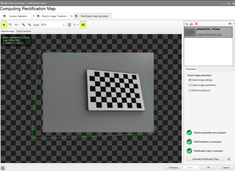
Add the RectifyImage filter. Connect the outImage to the inImage. Click on the filter and in the Properties window, and then click on the inRectificationMap input.
-
In the Calibration Editor you need to follow the exact same steps as it was described in the Calibration World Coordinates On Original Images example in steps 8-14 except for one additional step:
-
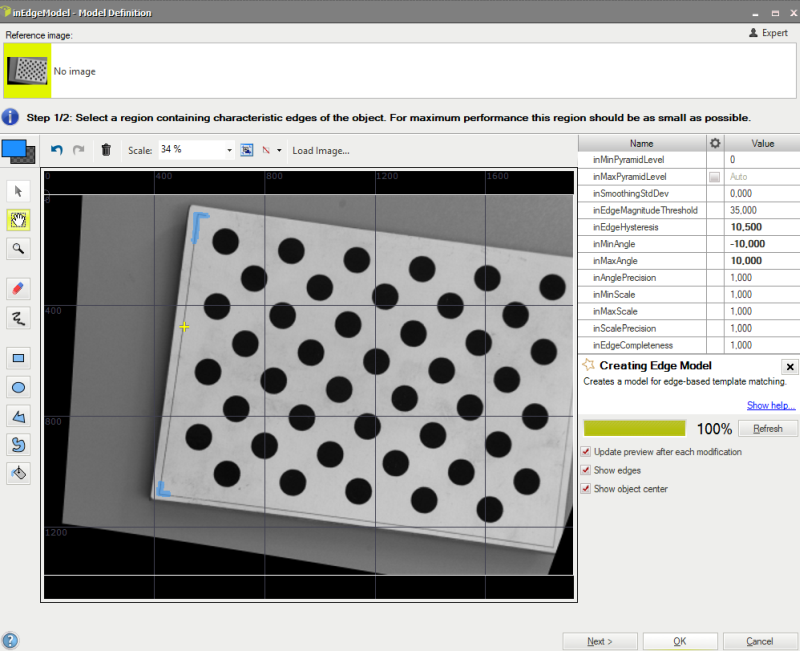
If you have prepared the rectification transform, now you can proceed with the algorithm - add the LocateSingleObject_Edges1 filter and create a new edge model by clicking on the inEdgeModel input in the Properties window of the filter. Create your model in a following way:
-
You can also narrow the search region down to accelerate computations by clicking on the inSearchRegion input in the Properties window of the filter and marking a suitable area. Additionally, to increase the accuracy of matching the template:
- Set the inMaxPyramidLevel to 2,
- Set the inMinScore to 0.6.
-
Now add two FitCircleToEdges filters. Connect the outImage to the inImage and the outObject.Alignment to the inFittingFieldAlignment (for both filters at once).
-
For both of the filters, determine the inFittingField, so that the circles are correctly fitted. Set the inEdgeScanParams.EdgeTransition to DarkToBright as circles are black. Right-click on the outCircle output, select Property Outputs and choose Center.
-
Now add the PointToPointDistance filter and connect the outCircle.Center from both of the filters to the inPoint1 and the inPoint2 respectively. This filter will allow you to calculate the distance in pixels between the centers of the circles.
-
To compute the world coordinates, use two ImagePointsToWorldPlane filters and connect the Center Points from the FitCircleToEdges filters to the inImagePoints input. Finally, connect the outRectifiedTransform to the inTransform in both filters.
Macrofilter Main
Used Filters
| Icon | Name | Description |
|---|---|---|
| FitCircleToEdges | Precise detection of a circular object or hole, whose rough location is known beforehand. | |
| RectifyImage | Applies a spatial map to distorted image transforming it to rectified image defined in world coordinates. | |
| EnumerateImages | Emulates image acquisition with images stored on disk. | |
| ImagePointsToWorldPlane | Finds the world coordinates of image Points. | |
| LocateSingleObject_Edges1 | Detection of an object whose outlines are sharp and rigid. Often one of the first filters in a program. | |
| PointToPointDistance | Measures the distance between two points. |
Further Readings
- Camera Calibration and World Coordinates - Detailed information about camera calibration and world coordinates.