
You are here: Start » Function Reference » Computer Vision » 1D Edge Detection » ScanExactlyNEdges_Direct
ScanExactlyNEdges_Direct
| Header: | FIL.h |
|---|---|
| Namespace: | fil |
| Module: | MetrologyBasic |
Locates a specified number of the strongest transitions between dark and bright pixels along a given path (without a scan map).
Applications: Very fast object detection (or presence verification) when the expected number of edges is clearly defined.
Syntax
void fil::ScanExactlyNEdges_Direct
(
	const fil::Image& inImage,
	const fil::Path& inScanPath,
	ftl::Optional<const fil::CoordinateSystem2D&> inScanPathAlignment,
	int inScanWidth,
	const fil::SamplingParams& inSamplingParams,
	const fil::EdgeScanParams& inEdgeScanParams,
	int inEdgeCount,
	fil::Selection::Type inEdgeSelection,
	float inMinDistance,
	ftl::Optional<float> inMaxDistance,
	ftl::Optional<const fil::LocalBlindness&> inLocalBlindness,
	ftl::Conditional<ftl::Array<fil::Edge1D> >& outEdges,
	ftl::Conditional<ftl::Array<fil::Gap1D> >& outGaps,
	ftl::Optional<fil::Path&> outAlignedScanPath = ftl::NIL,
	ftl::Optional<fil::Profile&> outBrightnessProfile = ftl::NIL,
	ftl::Optional<fil::Profile&> outResponseProfile = ftl::NIL,
	ftl::Array<fil::Path>& diagSamplingPoints,
	float& diagSamplingStep
)
Parameters
| Name | Type | Range | Default | Description | |
|---|---|---|---|---|---|
 |
inImage | const Image& | Input image | ||
|
inScanPath | const Path& | Path along which the scan is performed | ||
|
inScanPathAlignment | Optional<const CoordinateSystem2D&> | NIL | Adjusts the scan path to the position of the inspected object | |
|
inScanWidth | int | 1 -  |
5 | Width of the scan field in pixels |
|
inSamplingParams | const SamplingParams& | SamplingParams ( Interpolation: Bilinear SamplingStep: 1.0f SampleCount: Nil ) | Parameters controlling the sampling process | |
|
inEdgeScanParams | const EdgeScanParams& | EdgeScanParams ( ProfileInterpolation: Quadratic4 SmoothingStdDev: 0.6f MinMagnitude: 5.0f EdgeTransition: BrightToDark ) | Parameters controlling the edge extraction process | |
|
inEdgeCount | int | 0 - |
1 | Number of edges to be found |
|
inEdgeSelection | Selection::Type | Selection mode of the resulting edges | ||
|
inMinDistance | float | 0.0 - |
0.0f | Minimal distance between consecutive edges |
|
inMaxDistance | Optional<float> | 0.0 - |
NIL | Maximal distance between consecutive edges |
|
inLocalBlindness | Optional<const LocalBlindness&> | NIL | Defines conditions in which weaker edges can be detected in the vicinity of stronger edges | |
 |
outEdges | Conditional<Array<Edge1D> >& | Found edges | ||
|
outGaps | Conditional<Array<Gap1D> >& | Gaps between consecutive edges | ||
|
outAlignedScanPath | Optional<Path&> | NIL | Transformed input path | |
|
outBrightnessProfile | Optional<Profile&> | NIL | Extracted image profile | |
|
outResponseProfile | Optional<Profile&> | NIL | Profile of the edge (derivative) operator response | |
 |
diagSamplingPoints | Array<Path>& | Array of paths each one containing the sampling points that contributes to a single value of the extracted profile | ||
|
diagSamplingStep | float& | Used distance between consecutive sampling points on the scan path |
Optional Outputs
The computation of following outputs can be switched off by passing value ftl::NIL to these parameters: outAlignedScanPath, outBrightnessProfile, outResponseProfile.
Read more about Optional Outputs.
Description
The operation scans the image along inScanPath and finds a set of inEdgeCount image edges perpendicular to the path. If no subset (of inEdgeCount elements) of detected edges meets the requirements of inEdgeScanParams.minMagnitude, inMinDistance, inEdgeScanParams.edgeTransition then the outputs are set to NIL.
The optional parameter inScanPathAlignment defines a transform to be performed on the inScanPath so that the actual scan path (outAlignedScanPath) is adjusted to the position of the object, typically detected by one of Template Matching filters.
Note that in case of a scan path which is closed, the parameters controlling the distances between consecutive found objects do not control the distance between the first and the last of the found objects (counting from the beginning of the scan path).
Hints
- Set inEdgeCount to the number of edges that are to be found (the N number).
- Define inEdgeScanParams.EdgeTransition to detect a particular edge type, and only that type.
- If the expected number of edges cannot be found, try decreasing inEdgeScanParams.MinMagnitude. Verify this with the values on the outResponseProfile output.
- If consecutive edges are closer than 6 pixels apart, change inEdgeScanParams.ProfileInterpolation to Quadratic3.
- Adjust inMinDistance (in pixels) to filter out false edges that appear in proximity to other edges.
Examples
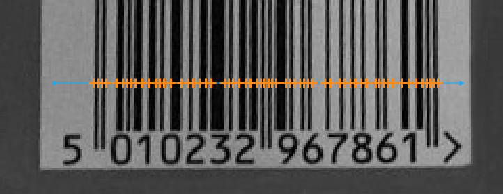
ScanExactlyNEdges_Direct locates the edges across inScanPath (inEdgeCount = 61).
Remarks
Read more about Local Coordinate Systems in Machine Vision Guide: Local Coordinate Systems.
This filter is a part of the 1D Edge Detection toolset. For a comprehensive introduction to this technique please refer to 1D Edge Detection and 1D Edge Detection - Subpixel Precision chapters of our Machine Vision Guide.
See Also
- CreateScanMap – Precomputes a data object that is required for fast 1D edge detection.
- ScanSingleEdge_Direct – Locates the strongest transition between dark and bright pixels along a given path (without a scan map).
- ScanMultipleEdges_Direct – Locates multiple transitions between dark and bright pixels along a given path (without a scan map).
- ScanExactlyNEdges – Locates a specified number of the strongest transitions between dark and bright pixels along a given path.