
You are here: Start » Program Examples » Blade
Blade
Aim
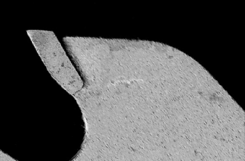
The task is to check whether a blade is broken.
Input
An image of a blade. The position of the object is variable, but limited.
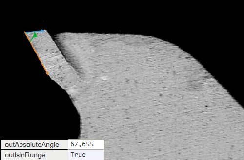
Output
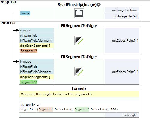
Calculated angle between the segments representing upper and left edges of a blade's tooth.
Hints
- As variations of the object positions are limited, you do not have to locate its exact position. Use the filters from Scan Edged 1D group to detect edged of a tooth.
- You can click on the output twice to change its name.
Labeling connections is explained in this article.
You can learn how to turn on sections here.
Solution (FIS)
-
Add EnumerateImages filter to get load consecutive images of some disk directory.
-
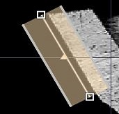
Setup fitting field like on the image below:
-
Set inScanCount to 25.
-
Set inScanWidth to 10.
-
Set inEdgeScanParams.MinMagnitude to 10.000.
-
Set inMaxIncompleteness to 0.700.
-
Label the outSegment as Segment1
-
Add another FitSegmentToEdges filter to find a segment that best matches the left edge points.
-
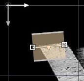
Add FitSegmentToEdges filter to find a segment that best matches the upper edge points. Connect to it the output of EnumerateImages.
-
Setup fitting field by clicking inFittingField in Filter Properties.
-
Set inScanWidth to 10.
-
Set inEdgeScanParams.MinMagnitude to 10.000.
-
Set inEdgeScanParams.EdgeTransition to DarkToBright.
-
Set inMaxIncompleteness to 0.700.
-
Label the outSegment as Segment2
-
To measure the angle between the found segments you can use a formula. You do not have to connect labeled outputs to the formula to be able to use them.
outAngle = angleDiff(Segment1.Direction, Segment2.Direction, 180)
Macrofilter Main
Used Filters
| Icon | Name | Description |
|---|---|---|
| FitSegmentToEdges | Precise detection of a straight edge, whose rough location is known beforehand. |
Further Readings
- Shape Fitting - This article presents usage of the Shape Fitting technique.
- Shape Fitting Filter Group - List of all filters used to perform Shape Fitting.