
You are here: Start » Program Examples » WebHmi Capsules
WebHmi Capsules
Aim:
The task is to inspect a quality of capsules and create a simple WebHmi. The following defects should be detected: black spots on the surface of a capsule and deformations of its shape.
Input:
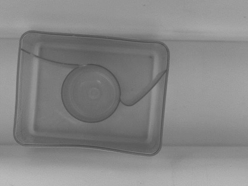
An image of a single capsule.
Output:
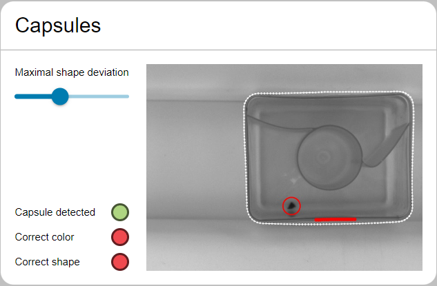
HMI containing an image with marked defects.
Hints:
The fastest and simplest way to detect the black spots on the capsule surface is the Blob Analysis technique. In order to detect shape deformations, you can delineate a path surrounding the undamaged capsule, thereby creating a path template, and compare it with the paths bounding the capsules appearing in subsequent iterations.
Labeling connections is explained in this article.
In the following articles, you can find information about designing a WebHmi and its Event Handling mechanism:
Solution (FIS):
-
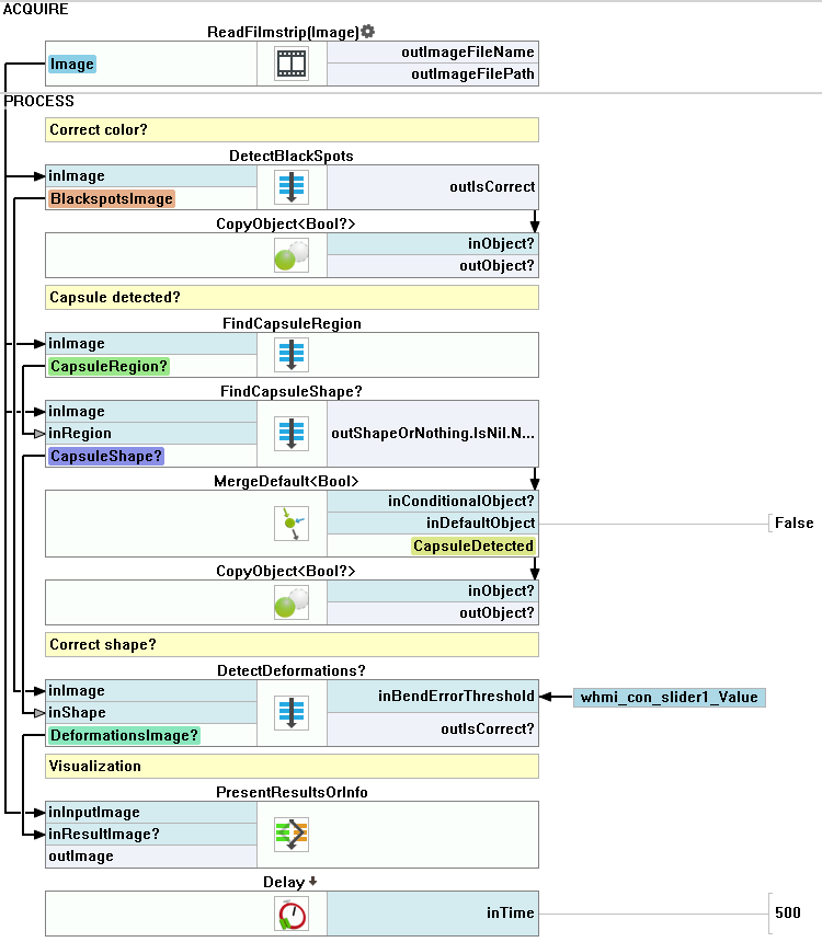
In the Workspace Explorer, open the workspace Examples, and in the Filmstrip window, select the Capsule dataset. Drag the Image channel to the ACQUIRE section.
-
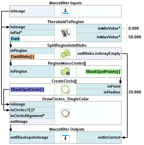
Create the Step macrofilter DetectBlackSpots and create the input of type Image. Place it in the PROCESS section.
-
As spots are much darker than the background, add the ThresholdToRegion filter. Set the inMinValue to 0 and the inMaxValue to 50.
-
Add the SplitRegionIntoBlobs filter to split the detected region into an array of regions corresponding to each stain.
-
Right-click on the outBlobs output, select "Property Outputs" and choose IsArrayEmpty from the list. The outBlobs.IsArrayEmpty output indicates whether the size of the array equals zero.
-
Drag the outBlobs.IsArrayEmpty and drop it on the Macrofilter Outputs block to create an output of the same data type. Name it outIsCorrect.
-
Add the RegionMassCenter filter and connect it with the outBlobs to find the center of each stain.
-
To create circles around stains, add the CreateCircle filter and connect its inPoint input with the RegionMassCenter filter's outMassCenter output. Set the former's inRadius input to 20.
-
To draw the result on the image, add the DrawCircles_SingleColor filter. Set the inColor input to red and the inDrawingStyle.Thickness input to 2.5.
-
Create an output outBlackSpotsImage and connect it with the outImage output of the DrawCircles_SingleColor filter.
-
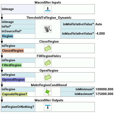
Create the Step macrofilter FindCapsuleRegion that will be tasked with finding a capsule-encompassing region. Add an Image-type input to it.
-
Add the ThresholdToRegion_Dynamic filter to create a region encompassing dark edges. Set both the inRadiusX and the inRadiusY inputs to 8. Moreover, set the inMaxRelativeValue input to -4.
-
Add the CloseRegion filter and set the inKernel input to Cross, then set both the inRadiusX and the inRadiusY inputs to 2.
-
Add the FillRegionHoles filter to obtain an extended region containing all the previously not included pixels that were nevertheless wholly enclosed by its boundaries.
-
Add the OpenRegion filter to perform a morphological opening so the noises can be removed.
-
Add the MakeRegionConditional filter to calculate the region area and check whether it falls within the specified range. Set the inMinimum input to 100000 and the inMaximum input to 125000.
-
Create an output outRegionOrNothing and connect it with the MakeRegionConditional's outConditionalRegion output.
-
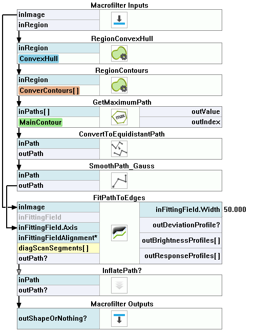
Create the Step macrofilter FindCapsuleShape and create inputs of types Image and Region. This macrofilter will be tasked with finding the contour of the capsule.
-
Add the RegionConvexHull filter and connect its inRegion input with the inRegion input of the macrofilter.
-
Add the RegionContours filter and connect its input with the outRegion output of the previous filter. It calculates an array of closed paths corresponding to the contours of the input region.
-
Add the GetMaximumPath filter to receive the path corresponding to the capsule outline. Connect its input with the outRegion output of the RegionContours filter.
-
Add the ConvertToEquidistantPath filter and connect its input with the output of the previous filter. Set the inStep input to 5.
-
Add the SmoothPath_Gauss filter to smooth out the output of the ConvertToEquidistantPath filter. Set the inStdDev input to 2.
-
Add the FitPathToEdges filter and connect the inImage input with the inImage input of the macrofilter.
-
Right-click on the inFittingField input and select Expand Structure Fields.
-
Connect the inFittingField.Axis input with the output of the SmoothPath_Gauss filter.
-
Set the following parameters of the FitPathToEdges filter:
- the inFittingField.Width input to 50,
- the inScanWidth input to 3,
- the inEdgeScanParams.SmoothingStdDev input to 1,
- the inEdgeScanParams.MinMagnitude input to 2,
- the inMaxInterpolationLength input to 20,
- the inMaxDeviationDelta input to 1.
-
Add the InflatePath filter to enlarge a path so that it corresponds to the external outline of the capsule. Connect the inPath input with the outPath of the FitPathToEdges filter.
-
Drag the outPath output of the InflatePath filter and drop it on the Macrofilter Outputs block to create an output of the same type. Name it outShapeOrNothing.
-
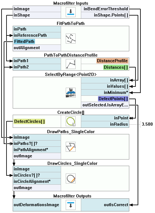
The task of macrofilters FindCapsuleRegion and FindCapsuleShape was to extract the contour of the capsule. Next, create a Step macrofilter DetectDeformations. In this filter, you will be calculating the distance between the outShapeOrNothing path and the model path. If the distance is longer than specified, the capsule is considered damaged.
-
Create the following inputs: inImage of type Image, inShape of type Path and inBendErrorThreshold of type Real.
-
Right-click on the inShape input, select "Property Outputs" and choose Points from the list to get access to the points of the capsule outline.
-
Add the FitPathToPath filter and connect its inReferencePath input with the input of the macrofilter. Set the following parameters:
- the inIterations input to 3,
- the inFirstShift input to 1,
- the inFirstRotation input to 3.
-
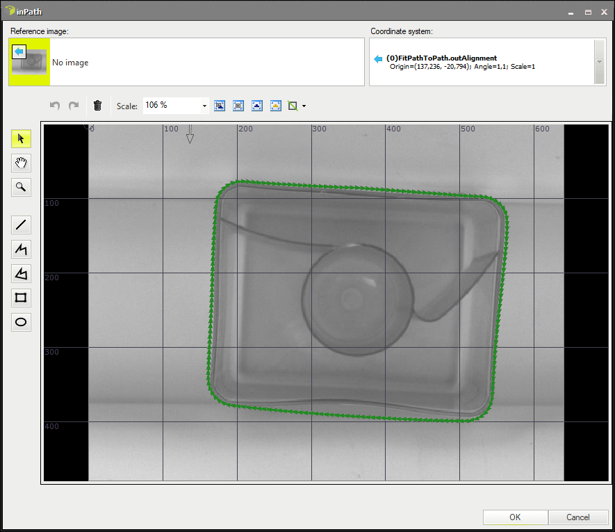
Click the "..." button at the inPath input to open the GUI for creating a path model.
- Select the FitPathToPath(#1)::outAlignment coordinate system.
- Create a closed path around the capsule.
-
To measure the distance between the paths, add the PathToPathDistanceProfile filter and connect its inPath1 input with the macrofilter input and the inPath2 input with the output of the FitPathToPath filter.
-
Add the ClassifyByRange filter to divide the input array into three output arrays, depending on the distance between the points of the paths. Focus on the array of points whose distance to the model path is higher than the specified maximum distance. Connect the following ports:
- the inArray input with the inShape.Points[] input data type.
- the inValues input with the outDistances output.
- the inMaximum input with the inBendErrorThreshold macrofilter input.
-
Right-click on the outHigher output, select "Property Outputs" and the IsArrayEmpty output from the list.
-
Create a macrofilter output outIsCorrect and connect it with the IsArrayEmpty output.
-
To draw the model path on the image, add the DrawPaths_SingleColor filter and connect its inPaths input with the outPath output. Set the following properties: the inColor input to white, the inDrawingStyle.PointShape input to Circle and the inDrawingStyle.PointSize input to 3.
-
To draw those parts of the contour where the capsule is deformed, add the CreateCircle filter and connect its inPoint input with the outHigher output. Then add the DrawCircles_SingleColor filter and connect its input with the outCircle output.
-
Create a macrofilter output DeformationsImage and connect it with the outImage output of the DrawPaths_SingleColor filter.
-
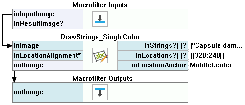
Create a Variant macrofilter PresentResultsOrInfo with the forking port inResultImage of the conditional type Image?.
- In the variant Nil add the DrawStrings_SingleColor filter. Connect its inImage input with the inInputImage macrofilter input.
- Specify the string to be drawn by setting the inString input to Capsule damaged or not present.
- Create a macrofilter output outImage and connect it to the output of the DrawStrings_SingleColor filter.
-
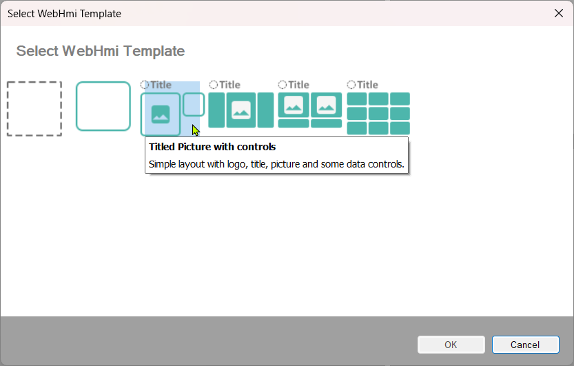
To add a WebHMI subsystem, choose Edit » Add Web HMI... and select a WebHMI template that fits the target layout. The template is just a starting point that can be freely modified. Here, the Titled Picture with controls template was used:
-
Arrange the WebHmi controls using the StackPanel controls.
-
To add new controls to the StackPanel, click
 the action button and choose the Add Content... option.
 -
Add and connect the Slider control to modify the Maximal shape deviation.
-
Add and connect the StatusIndicator controls.
-
Add TextBlock controls to attach a name to the Slider and StatusIndicators controls.
-
Connect the inputs and outputs of the created program with the WebHmi controls.
Macrofilter Main
Macrofilter FindCapsuleRegion
Macrofilter DetectBlackSpots
Macrofilter FindCapsuleShape
Macrofilter DetectDeformations
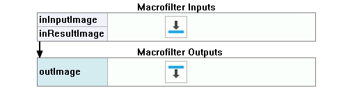
Macrofilter PresentResultsOrInfo(default)
Macrofilter PresentResultsOrInfo(Nil)
Further Readings
- Blob Analysis - Article presents detailed information about the Blob Analysis technique.
- Shape Fitting - This article presents usage of the Shape Fitting technique.